The OpenSCAD language
This language is based on only a few basic concepts. These concepts are quite elementary, but thanks to their combination you can generate any type of 3D structure.
This article is directly connected to the article OpenSCAD: how to create a solid 3D object, where a brief presentation of the OpenSCAD software and its usefulness is exposed.
In this article we will see the basic concepts that are behind the creation of a 3D object. These concepts are translated in a programming language and with a quick sequence of example you will do a general overview of how 3D models can be implemented.
Basic Shapes
- Cube
- Sphere
- Cylinder
- Polyhedron (not treated here)
CUBE
Defining a cube is very simple:
cube([width,heigth,depth]);
It creates a cube in the positive quadrant with one corner at (0,0,0).
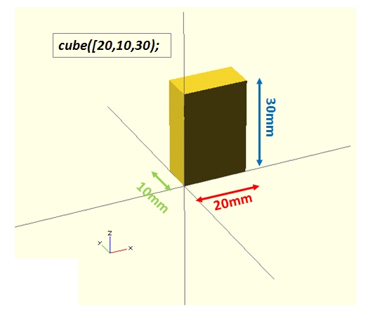
Instead if we want to draw a cube in the origin of the coordinate system we need to explicitly add the center parameter set as true (false by default).
cube([width,heigth,depth], center = true);
SPHERE
The creation of a sphere is very simple:
sphere(r);
It draws a sphere of radius r centered at the origin of the coordinate system.
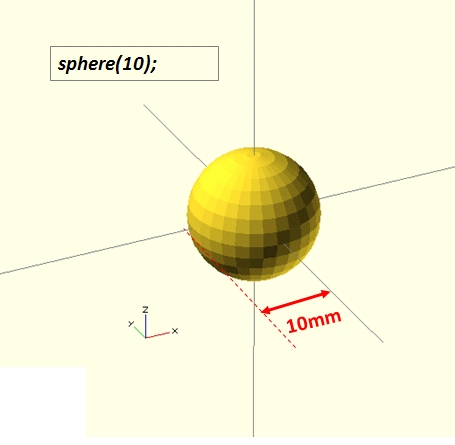
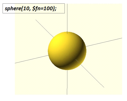
The sphere displayed appears, depending on its size, with the facets. If we want to increase the resolution in order to get a better “curved” surface we need to add the $fn parameter.
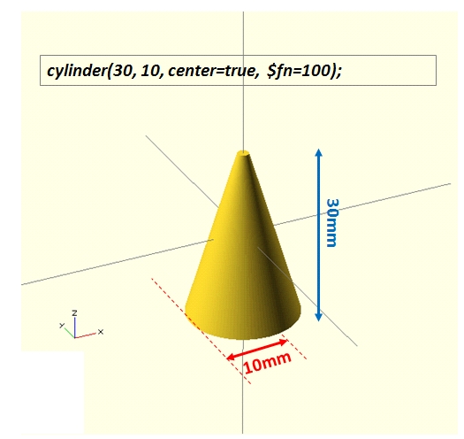
CYLINDER
The creation of cones and cylinder can be done by the same function.
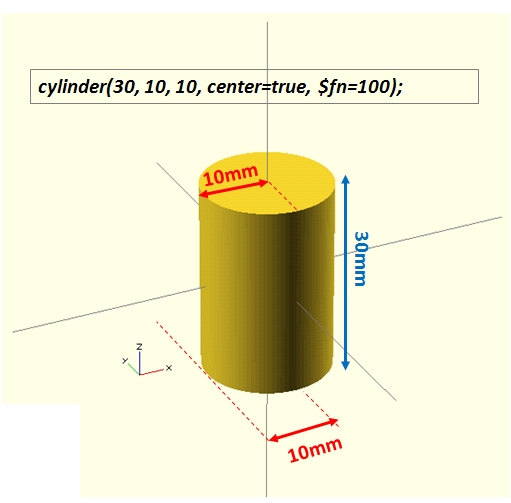
Defining only a radius we get a cone:
cylinder(h,r,center=true,$fn = 100);
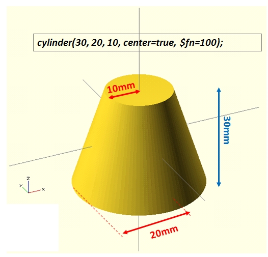
Defining two radius we get a truncated cone, or a cylinder (if r1 = r2):
cylinder(h,r1,r2,center=true,$fn=100);
Transformations
Once you define a 3D shape to be drawn, it is necessary to subject it to the transformations. if you’re familiar with the basics of math (matrix algebra) that are behind the 3d modeling, you should know that any transformation to which an object is subjected, can be divided into a series of elementary transformations.
- translation
- rotation
- scaling
- mirroring
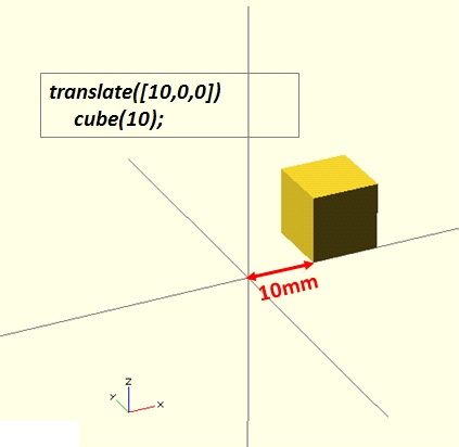
TRANSLATION
Translation means moving an object by a distance in a specific direction.
translate([x,y,z])
“an object”;
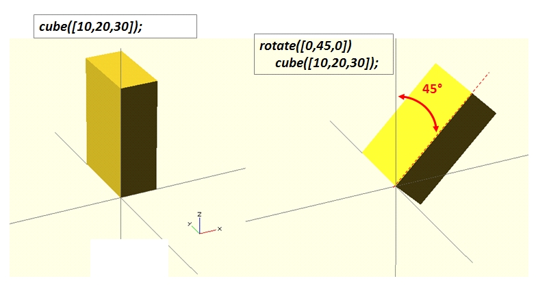
ROTATION
This transformation rotates an object about the origin of the coordinate system or around an arbitrary axis.
rotate([ax,ay,az])
“an object”;
where ax, ay and az are the angles of rotations with respect to the x-axis, the y-axis and the z-axis respectively.
SCALING
With the scaling transformation we can shrink and stretch a model along an axis. Often, this transformation is used in order to obtain other shapes which are not not obtainable with the basic shapes. A non-uniform scale on a specific axis deforms a basic shape and doing so we get a new and more complex shape. A good example may be very evident if we apply it to a sphere.
scale([x,y,z])
“an object”;

MIRRORING
This transformation mirrors the object on a plane through the origin.
mirror([nx,ny,nz])
“an object”;
The argument of the mirror() function is the normal vector of a plane intersecting the origin through which to mirror the object.

CSG Operations
Once we have defined a set of 3D objects and applied them a sequence of transformations, the third operation to do is combining them. The combination of different object could be done with the CSG operations:
- union
- difference
- intersection
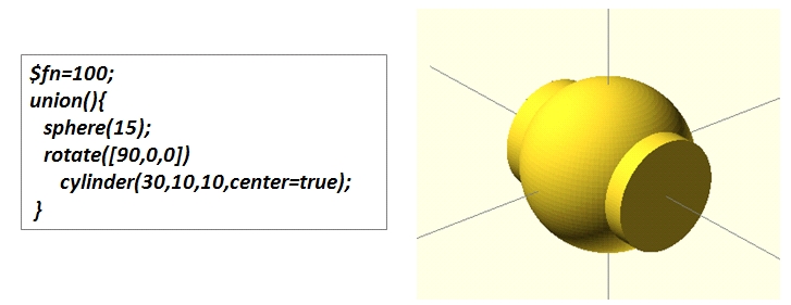
UNION
The union generates a new 3D object defined by the volume occupied by all objects subject to union.
union(){
“object1”;
“object2”;
…
}
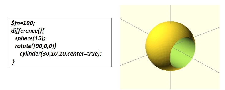
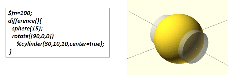
DIFFERENCE
The difference generates a new 3D object defined by the volume occupied by the first object minus the second.
difference(){
“object1”;
“object2”;
}
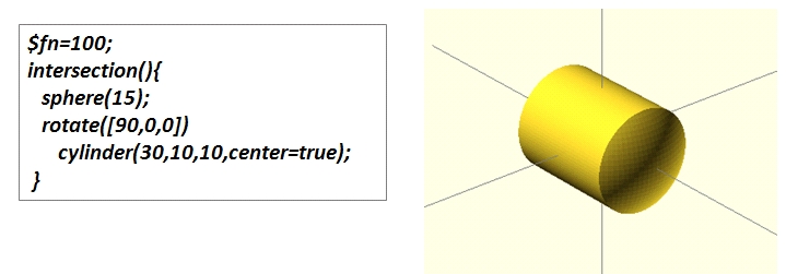
INTERSECTION
The intersection generates a new 3D object defined by the volume occupied by both the objects.
intersection(){
“object1”;
“object2”;
}
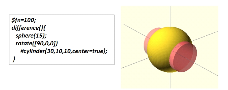
MODIFIER CHARACTERS
There are a set of characters (‘%’ and ‘#’) which are used to change the appearance of the objects. They are particularly useful when we want to highlight the volume excluded from the previous CGS operations.
The ‘#’ character is the debug modifier and draw the corresponding object in transparent pink
The ‘%’ character is the background modifier and draw the corresponding object in transparent gray.
In next articles some tutorial for implementing complex 3D structure will be presented. Furthermore, some topics not covered here (due their complexity) will be discussed in detail : the hull function, the Minkowski sum and the extrusion from 2D shapes.
GET INVOLVED
If you are an expert and you wish to talk about these topic by yourself. You’re welcome. Or you have developed some complex shape and you wish to share with the world. Please login and send me an article/post or tutorial. I will publish it soon.
So, see you soon!