Fritzing is the right software for those who want to represent in a realistic and simple way an electric diagram during a tutorial, the writing of an article. If you are a fan of Arduino, if you delight in designing electrical circuits and then converting them into PCB printed circuits, you will soon find that fritzing is a valuable support both in the educational and professional field.
Lately browsing here and there on the net, probably looking for some tutorials, you have happened to see a series of images that show the diagrams of prototypes with a graphics very pleasant and realistic as ever (see Figure 1).
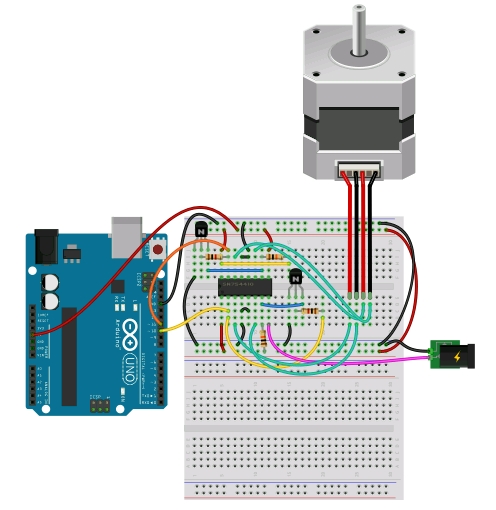
Not only the breadboard but also all the components, the boards, the motors and even the sensors, are represented in a very faithful way. Moreover, the connections between the various electrical components are represented by real coloured cables. Everything makes the scheme very explanatory and much simpler to interpret, especially when you want to write tutorials where you need to direct the reader step by step to the creation of a circuit on a prototype.
The software that allows us to do all this is fritzing, an open-source tool directly downloadable from the official website (http://fritzing.org/download/); It is totally free and does not require any registration. Fritzing is an EDA (electonic Design Automation) software and is much more than just a graphical editor of electrical diagrams. In fact, once the schematic of the electric circuit that we want to realize is completed, it is able to provide us with the PCB scheme to be printed (or sent to the site of fritzing).
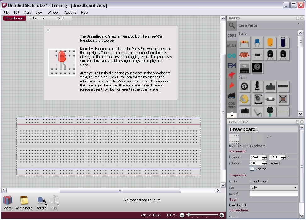
Once you download the latest version of the software fritzing on our computer, and launched the program, it will open a window as shown in Figure 2. The application allows us to edit our projects on three different elevations (Views):
- Breadboard View
- Schematic View
- PCB View
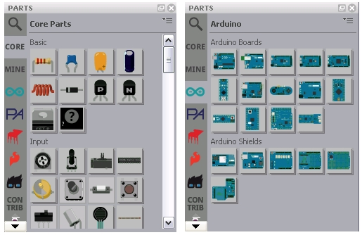
The Breadboard view looks like the default view (the first that appears when the application opens). A grid and breadboard (identical to those that can be found around) are the starting point for the creation of our projects. At the top right there is a section where all the components, tabs, shield, motors, sensors, etc. (see Fig. 3) that are available within the application are listed. Moreover, the search for these components or cards is further facilitated by the icons representing the production companies of these components (Arduino, parallax, Picaxe, Sparkfun, etc.).
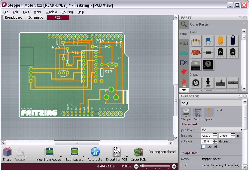
Once we have selected the components that we need, we drag them one by one into the prospectus, thus completing the scheme that we had chosen. Once realized our protype we can go to analyze it through the other two views. In the Schematic View we will have a representation closer to the professional diagrams used in engineering (see Fig. 4).

While in the PCB view we can manage how the components will appear physically on the PCB (Printed Circuit Board).

Fritzing is the suitable software for those who need to represent realistic and simple circuit diagrams, for example, when you need to present a tutorial or write an article on Web. If you are a fan of Arduino or if you enjoy designing circuit diagrams, you will soon find that fritzing is a valid tool both educationally and professionally. For instance, you can easily convert your circuit diagrams into printed boards (PCB).
Lately browsing here and there on the net, probably looking for some tutorials, you have happened to see a series of images that show the diagrams of prototypes with a graphics very pleasant and realistic as ever (see Figure 1).
Not only the breadboard but also all the components, the boards, the motors and even the sensors, are represented in a very faithful way. Moreover, the connections between the various electrical components are represented by real coloured cables. Everything makes the scheme very explanatory and much simpler to interpret, especially when you want to write tutorials where you need to direct the reader step by step to the creation of a circuit on a prototype.
The software that allows us to do all this is fritzing, an open-source tool directly downloadable from the official website (http://fritzing.org/download/); It is totally free and does not require any registration. Fritzing is an EDA (electonic Design Automation) software and is much more than just a graphical editor of electrical diagrams. In fact, once the schematic of the electric circuit that we want to realize is completed, it is able to provide us with the PCB scheme to be printed (or sent to the site of fritzing).
Once you download the latest version of the software fritzing on our computer, and launched the program, it will open a window as shown in Figure 2. The application allows us to edit our projects on three different elevations (Views):
- Breadboard View
- Schematic View
- PCB View
The Breadboard view looks like the default view (the first that appears when the application opens). A grid and breadboard (identical to those that can be found around) are the starting point for the creation of our projects. At the top right there is a section where all the components, tabs, shield, motors, sensors, etc. (see Fig. 3) that are available within the application are listed. Moreover, the search for these components or cards is further facilitated by the icons representing the production companies of these components (Arduino, parallax, Picaxe, Sparkfun, etc.).
Once we have selected the components that we need, we drag them one by one into the prospectus, thus completing the scheme that we had chosen. Once realized our protype we can go to analyze it through the other two views. In the Schematic View we will have a representation closer to the professional diagrams used in engineering (see Fig. 4).
While in the PCB view we can manage how the components will appear physically on the PCB (Printed Circuit Board).