The increasing use of electrical and electronic equipment especially sensitive to surges in low-voltage networks, has made it essential the implementation of protection systems more efficient and targeted particularly to the type of system where such protection is necessary.
The modern electronic devices, even in the home, such as: local computer networks, computers, televisions, telecommunications equipment, robotic appliances, alarm systems and video surveillance, home automation systems, are more subject than in the past to be damaged by surges.
Power surges are the main cause of failure of the electronic devices, the most dangerous are caused by:
- lightning;
- electrical operations on the distribution line;
- parasitic interference.
Indeed a possible failure, caused by a surge voltage, can lead to loss of service and / or data and / or productivity far above the cost of any protection equipment.
The devices that perform an effective surge protection on the HV and MV networks are called “surge arresters“, while those who perform on the low-voltage networks are referred to as “surge protectors” SPD (Surge Protective Device). It may be concluded that the SPD devices pursue the activity of “gatekeepers” within an electrical installation, allowing safe use as it is also drastically reduced the possibility of a fire risk.
Currently the IEC 64-8 takes into account the surge protection of a power plant through the recommendation of the use of the SPD. In particular, it requires that the main protective conductor must reach directly, without any interruption, a ground terminal block inside the main switchboard precisely in order to allow efficient installation of surge protectors.
Technical characteristics of voltage surges
A surge is defined as an abnormal value of voltage which exceeds the peak value of the maximum steady-state voltage, present in a given plant in the ordinary conditions of operation.
In practice, they are constituted by voltage spikes propagating on the power line. They are typically shorter than 1 ms with an amplitude that can reach a value more than 20 times that of the nominal supply voltage. The consequences of this transient increase in voltage can be: insulation failure, short circuits with possible triggering of fire and / or explosion, melting of conductors, destruction of equipment.
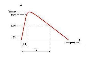
The graph in Figure 1 shows the trend of an overvoltage surge, where T1 is the rise time expressed in microseconds, and represents the time interval between the instants in which the pulse is at 10% and 90% of the value of peak. T2 is the ‘time to 50%’ expressed in microseconds, and represents the time interval between the instants in which the pulse is at 10% and 50% of the peak value; Vmax is the peak value of the surge.
Power surges can be distinguished based on the way of propagation:
– Common mode surges (MC) or longitudinal. They occur between active conductors and the ground and are especially dangerous for the equipment having the ground connected to the earth, Figure 2;

– Surge differential mode (MD) or transverse. They occur between active conductors, phase/phase or phase/neutral isolated and are especially dangerous for all type of electronic equipment and for those concerned with data processing, as shown in Figure 3.

Depending on their origin:
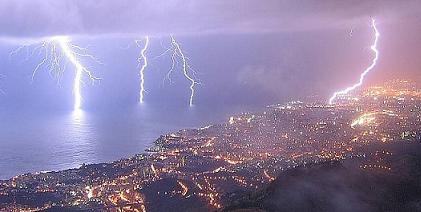
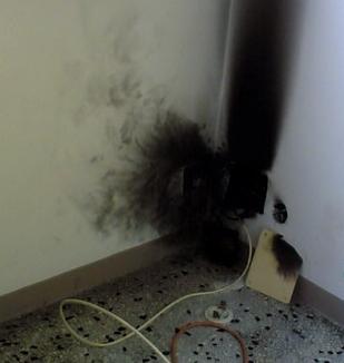
– atmospheric origin, LEMP (Lightning ElectroMagnetic Pulse). In this case the surges could be of two different types: conducted, if the lightning strikes directly or in the immediate vicinity of an airline (electricity or telecommunications), resulting in lightning currents that propagate also inside housing; induced, if the lightning strikes the ground. The electromagnetic energy developed in response to a lightning strike and which invests all conductors, can generate surges both common mode differential mode. These surges, spreading by conduction, in turn generate an electromagnetic field which induces a surge on the conductors which can take values of several tens of kV. Fig.4 shows an example of the effects of this type of surges.
– maneuver origin, SEMP (Switching ElectroMagnetic Pulse). These surges are due to an abrupt change in the condition of the system within an electricity network that cause the birth of damped transients or waves surge with high frequency. This type of surges can be generated by: maneuvers of interruption or switching circuits, maneuvers of control, start or stop of motors, insertion of capacitor banks. This type of surges, compared to those of atmospheric origin, have a lower energy content but occur with greater frequency. They have a short duration and due to the peak value and the sharp edge, cause a strong wear of the electrical systems in a particular way of electronic equipment.
– industrial frequency temporary surges. These surges are those that have the same frequency of the supply system and are due to: breakage of the neutral conductor resulting imbalance of the phase voltages; fault isolation phase/mass or phase/earth on a circuit with isolated neutral; intervention of arresters on MV lines with a consequent rise in the ground potential of the plant; failure MV/LV in the cabin.
– Electrostatic origin, ESD (Electro Static Discharge). These surges are due to accumulation of electric charges and can occur especially in dry environments where they accumulate electrical charges which generate very high electrostatic fields. A practical example is when you are walking on a carpet wearing shoes with rubber soles. You can load at a voltage of several kV, and if you get closer to the casing of an appliance, so electrostatically charged, you discharge the stored energy causing a spark of some amps. This may cause damage to the electronic boards of the appliance.
Surge protectors are divided into two categories:
– Primary. It consists in the protection of the plant by the fall of a direct lightning strike and is made outside of the buildings. This protection bases its functioning on the presence of a sensor, a metal structure placed in a higher position than the other structures to be protected. The most widely used primary protection is the traditional lightning protection system LPS (Lightning Protection System) consists of sensors and sinks. In order to assess the possible risk of electrocution of a given structure, the graphs shown below can be of great help. In particular, Fig. 5 shows the average value of Nt (density of lightning to the ground). CEI 81-3 shows the value of Nt for all the Italian municipalities. This parameter is critical to the design of the LPS. Fig. 6 shows the frequency of storms in Italy in relation to the month. More information about lightning storms and fall in real time can be obtained from the following sites: meteosestola, centrometeo,fulmini, meteolive;


– Secondary protection is realized within buildings and serves to reduce the effects of lightning surges, for maneuver and industrial frequency. The secondary protection is classified according to the method of connecting and is divided into: protection in series built for a specific equipment to be protected ( stabilizers network, filters, transformers, UPS); protection in parallel which is the most widely used secondary protection for both power networks for the telecommunications.
In this article we will consider the protection in parallel, in particular the surge arresters SPD (Surge Protective Device) whose purpose is to drain the energy of the surge to ground, limiting it to acceptable levels by the equipment connected to low voltage installations .
In these systems, in fact, the surges are the main cause of failure of the electronic devices and interruption in production. Now the electronic systems are becoming more common, even in the home. With the process of miniaturization of circuits and components, electronic devices are subject to be damaged by surges more than in the past. Especially in cities with a high population density, the effects resulting from electrical surges from lightning can occur for several miles with devastating results.
With the Italian System of Lightning Detection (SIRF) at CESI in Milan, it was noted that each year the Italian territory is hit by an average of about 1.5 million lightning. Appropriate tests have shown that the maximum temperature of a lightning bolt can reach up to 30 000 ° C for a duration of about one millionth of a second, and its speed can vary from 30,000 to 100,000 km / s. Even the electrical parameters are huge: the highest peak value of the current detected is 350 kA; the voltage between the cloud and the ground, before initiation of the discharge, can reach values of a few hundred million volts.

The main components of the SPD
Unfortunately there is no complete component that fully meets all the technical requirements for an effective surge protection. Instead different components complementing each other are used in a combined technology. In fact, the different components are often combined in order to optimize protection. Consequently, the SPD are divided into three families:
- with initiation or switching;
- with limitation;
- combined type, obtained by connecting in series or parallel spark gaps, varistors and suppressor diodes.
In practice three main components are used:
– Spark gaps. They belong to the type with primer. Above a certain voltage value, these components trigger an electric discharge inside them, acting as a short circuit at the moment. They consist of two electrodes suitably spaced apart, and to the occurrence of an overvoltage, an electric arc is triggered between them that transforms the spark gap in a short circuit to ground. They are defined as follows: in the air, mostly used as surge arresters on HV and MV networks, in which the trigger voltage depends not only on the distance of the electrodes also by environmental conditions such as temperature, air pollution, pressure; gas or GTD (Gas Discharge Tube), which are mainly used as surge arresters SPD on low-voltage networks. These are contained in sealed ampoule containing rare gases such as argon and neon. the gas spark gaps have a very high ability to download up to 100 kA, a very long life and small size;
– Varistors belong to the type with limitation, in practice they are nonlinear resistors, generally formed by disks of zinc oxide or silicon carbide, which does not comply with Ohm’s law, ie, their resistance is inversely proportional to the potential difference applied to them heads; in practice, not just the nominal voltage is exceeded, its resistance drops rapidly until it becomes a conductor. The varistors have the advantage of having a high discharge capacity of up to about 80 kA, with a reaction time of about 20 ns and a very low residual voltage; by contrast they present a high capacitive value which can introduce noise in high-frequency circuits for which it is not advisable their use in telecommunications systems;
– Diodes suppressors. They are in practice Zener diodes but which have a higher speed and may be unidirectional or bidirectional; starting from a certain breakdown voltage, they rapidly become conductors, and thus short-circuiting the overvoltage.
The functioning of SPDs
The main function of an SPD, in a given electrical system, is to divert the surge current to ground and consequently limit the overvoltage, for which its operation can be described by analyzing the phenomenon of surge in three phases:
– Normal operation in the absence of overvoltage. The rated voltage of the system Un is present at the ends of the SPD, for example, 230 V. This voltage can vary over time within a tolerance band between 207 and 253 V (+/-10%). For this reason, the SPD shall have a continuous operating voltage Uc significantly above 253 V, as we have to consider, in addition to the voltage drop along the links, also the voltages UT (TOV Temporary Transient Overvoltage), that is the tolerated temporary overvoltages that are present on line and caused by the distributor for maneuvering; in this condition of normal operation, due to the fact that the device does not have infinite impedance but very high, it will be continually crossed by a leakage current to ground Ic (current continuous operation) of the order of μA; in practice, the device has no influence on the electrical system in which it is installed;
– Operation during a surge. At the occurrence of a voltage higher than the value of Uc, in a time of a few nanoseconds, the SPD reduces its impedance acting as a conductor. During this action, by virtue of the fact that the device is not zero but very low impedance, a value of residual voltage is established at its ends. This voltage is defined protection level Up. In this phase, an important value is the value for the rated current In of discharge that is defined by proving the SPD with the waveform of the current of 8/20 microseconds. Moreover, in this phase is another important value is the Imax value, which is the peak value of the maximum current that the SPD is able to bear at least once without damage; typically the Imax value is twice that of In;
– Extinction of the surge. Once the surge ceased, the SPD assumes its original impedance and return to normal operating condition.
The characteristic parameters of the SPD
The rise time T1 and time-to-50% T2 are shown in Figure 1. They are used to achieve pulse standardized test and define the SPD according to the classes of protection as defined in the standard EN 61643-11.
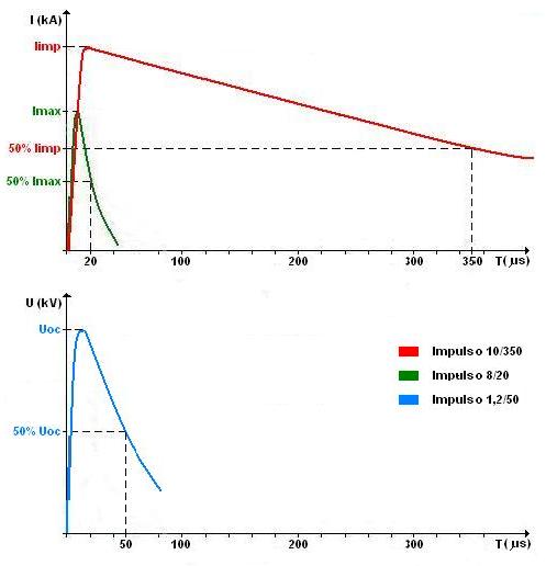
Figure 7 shows the waveforms used standardized, in particular:
- the waveform of long duration 10/350 μs, which simulates a direct lightning strike a high energy content;
- the waveform of short duration 8/20 μs to low energy content that simulates an indirect lightning strike or electrical maneuvers on the distribution line or parasitic interference;
- the waveform of short duration Uoc 1.2 / 50 μs delivered by a test generator combined simultaneously with a current pulse with the form of wave 8/20 μs for the verification of safety class III.
With these waveforms you can define the following characteristic parameters of the SPD:
- Current pulse (Iimp) is the peak value of the current that circulates in the SPD and that has a waveform 10/350μs;
- Nominal discharge current (In) is the peak value of the current that circulates in the SPD and that has a waveform 8/20μs;
- Maximum discharge current (Imax) is the peak value of the maximum current that can circulate in the SPD without damaging it and that has a waveform 8/20μs;
- Circuit voltage (Uoc) is the peak value of the load voltage waveform 1,2 / 50μs, produced by a generator at the same time combined with a current waveform 8/20 μs;
- Protection level (Up) is the maximum value of the instantaneous voltage across the terminals of the device during its protection function or the value of voltage of the load when the device is subject to surge; this parameter must be less than the impulse withstand voltage of the equipment connected to the system;
- Effective protection level (Up/f) is the real value of Up increased by the voltage drop across the connecting wires and the switching voltage surges UT present on the line caused by switching operations of the distributor;
- Maximum continuous voltage or rated voltage (Uc) is the maximum value of the rms voltage that may be continuously applied to the device;
- Protection distance (d) is the maximum allowable distance between the device and the equipment to be protected.
With these parameters, but especially with the protective distance d, the following classes of protection are definited:
- class I. In order to belong to this class, the SPDs shall be tested with the nominal discharge current In and the current pulse Iimp. The SPDs in this class offer a level of protection up to 4 kV and can be installed on the main distribution or at the entrance of the buildings, at the start line in switchboards, secondary and on end. In practice, the SPDs of this class are suitable to handle the currents of direct lightning strike;
- class II. In order to belong to this class, the SPDs shall be tested with the rated current In and download with maximum discharge current Imax. The SPDs in this class offer a level of protection of 2.5 kV and can be installed in the distribution board or on end. In practice, the SPDs of this class are suitable to handle the currents of induced surges;
- class III. In order to belong to this class, the SPDs shall be tested with the generator combined with open circuit voltage Voc and waveform 1,2 / 50 μs, at the same time with a current pulse waveform 8/20 μs. The SPD in this class offer a level of protection of 1.5 kV and can only be installed on end. In practice, the SPD of this class are suitable to be installed exclusively in the user sockets.
The impulse withstand
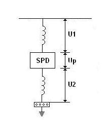
A key criterion for the choice of the SPD most suitable in a given electrical system concerns the impulse withstand, that is, the coordination between the level of impulse withstand of the insulation of the connected equipment and the level Up of the SPD to be used. In fact, the surge protection (see Figure 8) is effective only when the level Up of the SPD, plus the voltage drop U1 + U2 across its connecting wires, is less than the impulse Uwithstand of the equipment to protect.
From the above disclosure, it is deduced that the realization of very long connections introduces voltage values that are added to the value of Up and can make vain the protection offered by the SPD; for example, in the case of the SPD to varistors each meter of cable corresponds to a value of U1 or U2 of about 1000 V. In general, if it is satisfied the relation Up + U1 + U2 tenuta, it can be said that the coordination of the estate of the insulation is satisfied. Thus the user devices are adequately protected against overvoltage. Regarding the Utenuta IEC 60664-1 identifies and defines four categories of Utenuta in function of the nominal voltage; For example, with a rated voltage 230/400 V you must have:
- Category I: impulse withstand voltage 1500 V, includes all sensitive electronic equipment such as computers, televisions, telephones and telecommunication equipment, etc.;
- Category II: impulse withstand voltage 2500 V, includes all the equipment to use normal household appliances such as type dishwasher, washing machine, refrigerator, etc.;
- Category III: impulse withstand voltage 4000 V, includes all fixed electrical installation such as electrical panels;
- Category IV: impulse withstand voltage 6000 V, includes all components and equipment located upstream of the main switchboard (switchboard) such as the the upright, the counter, the main means of protection.
Regarding the assessment of the suitability of a specific item of equipment to withstand the stresses of atmospheric origin and therefore belonging to a certain category, an acceptance test called “test pulse” has been defined. This test is performed on the main devices of the plant during its construction and it consists of applying a waveform standardized 1.2/50μs represented in Fig.7. Pulses of this type are obtained by means of a special equipment called pulse generator.
The protection of the SPD
In its normal use, the SPD produces practically a short circuit, in this case the limiter can interrupt the resulting current and resetting, only up to a certain value of short-circuit current; above this value the SPD requires an upstream device, properly coordinated, capable of interrupting said current. Devices suitable for this type of protection can be either circuit breakers or fuses. The surge arresters as well as with the cables, are designed to withstand certain levels of let-through energy beyond which one has the total destruction of the limiter with the possibility of serious injury or fire.
Regarding the protection against indirect contact, in a system protected with SPD, you should insert a differential device coordinated with the earthing system which interrupts the fault current to ground without causing unwanted tripping. When you are near the point of connection to the distributor network, devices suitable for this type of protection are selective differential switches. In most cases it is the same manufacturer that provides information and diagrams on how to protect their SPD.
Some precautions for installation
To ensure an effective protection, following a series of measures to be implemented in the installation phase of the SPD are reported:
- The SPD must be connected to the same equipotential bar to which the earth of the equipment to be protected is connected, as shown in Figure 9;
- Especially for the SPD of class I, when they are placed for the protection of the main distribution and therefore they are affected by the impulse current Iimp, the sum of the length of the connection cables upstream and downstream of the SPD shall not exceed 50 cm, as shown in Figure 9;

- In the event the connecting cables of the SPD are greater than 50 cm, it is advisable to carry out the in-out, making sure that the cables are kept as far away as possible from each other, as shown in figure 9;
- In order to avoid the formation of induced surges, it is absolutely necessary to avoid routing the ground wire that connects the SPD together with conductors protected;
- It is not enough to install an SPD of Class I in a general switchboard at the end of a line, such as a switchboard in a flat, thinking that in this way you have protected all that is situated downstream. The distance of protection is highly dependent on the voltage impulse Utenuta connected devices. To ensure the protection offered by the SPD, it is necessary to check that the effective protection level Up/f of the SPD is less than half the Uwithstand device to be protected. An SPD class I at the start line only decreases the probability of destruction of the plant and the formation of dangerous fires but it absolutely does not protect the equipment at the end of the line. For an effective protection you need to create a system composed of an SPD of Class II close to the individual devices or groups, and an SPD Class III for all sensitive electronic equipment such computers, televisions, video surveillance system, home automation system, phone line, etc. It is appropriate, however, that this type of coordination be realized in accordance with the features provided by the manufacturer of the SPD.