Introduction
The digital broadcast television, beyond inevitable problems of realization and running mainly due to a choice too hasty without having carried out before a better dislocation of transmission sites with their radiation patterns, represents an important step towards the realization of future services of interactive TV sets. These interactive services will be added to the simple reception of television programs, thus transforming the television into a true interactive computer through which you can take advantage of many services.
The digital broadcast television in Italy is based on the European standard Digital Video Brodcasting (DVB) designed for digital television broadcasts via ground (DVB-T), cable (DVB-C) and satellite (DVB-S). This digital television standard, now fully realized in our country, will provide the following advantages over analog transmission:
– Considerable enhancement of the television programs as quantity. This is because, with the digital television broadcasting and on the same radio frequency band occupied four different programs countless more information and interactive utility can be transmitted in place of one analog program. Without more information and significantly reducing the quality, it is possible to transmit up to eight different programs;
– Considerable enhancement of the television programs like quality. The DVB standard allows the transmission of high quality images and sound, allowing the use of the format 16:9 instead of the traditional 4:3 (this format is the ratio between the horizontal and vertical dimensions of the image) and then the TV viewing is possible with very large screen without any degradation of image definition, also limiting the number of programs in one channel images with high definition (HD) can be transmitted;
– For the same service area, lower transmit power amplifiers are used since extra protection against interference and noise is guaranteed;
– Creation of national networks in isofrequency Single Frequency Network (SFN);
– Provision of several additional interactive services. Through the use of the latest generation of TVs you can treat and store the information and, through connection to the telephone line or mobile phone, you will have access to Internet services such as MHP (Multimedia Home Platform) for multimedia services to users domestic.
All this means that without moving from home and in a simple way, household users will have a wide range of video programs of excellent quality as well as a wide range of tasks that today require displacements in particular places such as banking, postal, administrative procedures or the use of a computer, operations that in many cases are still is difficult to understand. Figure 1 shows the digital transmission system DVB-T.
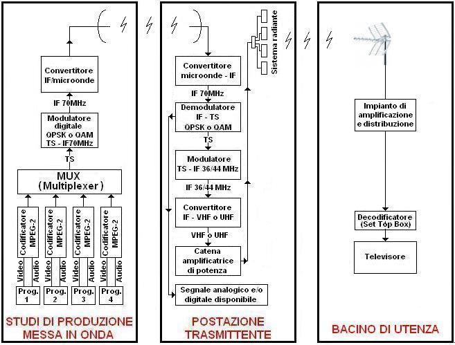
Production and broadcasting studies
Studies of the production and / or broadcast shall provide its audio and video signals properly digitized. In the case of figure 1, you can see four different programs, that are applied to four encoders which ensure to encode them digitally according to the MPEG-2 standard.
The four coded signals are sent to the input of a multiplexer (MUX) that provides a single digital data stream as output, called Transport Stream (TS). The transport stream thus generated and compressed is applied to a digital modulator which supplies at the output a modulated carrier at intermediate frequency IF of 70 MHz according to the systems QPSK or 16-QAM or 64-QAM which is then converted into microwave and transmitted to the transmitting via radio relay communication.
The transmitting party
The microwave signal is received from the transmitting party, generally located at high height above sea level with the possibility to serve vast areas of user. From here, the signal is again converted to the intermediate frequency of 70 MHz and demodulated to regain the TS with the information of the four programs.
At this point, the TS can be connected directly to a modulator which provides a modulated carrier wave as output to the intermediate frequency of 36 ÷ 44 MHz according to the standard OFDM for the DVB-T (for example, the United States and the ATSC system and the standard 8VSB). This frequency is then converted to VHF or UHF band through the chain of high power amplification or can be used for other broadcasts such as analogical ones or made available for other radio links to other transmitting stations.
The signal, once it is converted into a channel in the VHF bands (band I 47÷68 MHz channels E2÷E4 and Band III 174÷230 MHz channels E5÷E12 ) or UHF (band IV 470÷606 MHz channels E21÷E37, band V 606÷790 MHz channels E38÷E60), is connected to the radiating system which provides its own radiation pattern suitably designed to radiate the signal in order to serve a particular catchment area.
The catchment area
The signal transmitted through the radiant system is received by the user, through an appropriate antenna system relatively to the service of transmitting. It is made visible on the television through the use of a decoder device that in case of old televisions can be external to the receiver (set top box) or IRD (Integrated Receiver Decoder) integrated in the receiver in case of televisions the latest generation .
The MPEG-2 encoder
In order to make a successful digital terrestrial broadcasting, it is necessary that the video and audio information are generated directly in digital form or as happens in most cases, the information in analog form must be converted to digital.
In fact, most of the broadcasters, instead of completely replacing all analog production equipment (cameras, video and audio mixer, matrix switchers, monitors, or other devices to study, etc.) still prefer much more economically convert the signal analog to digital. In practice, the video signal and analog audio generated by the studio or leaving the broadcasting, before being sent to the MPEG-2 encoder, are converted to digital.
Unfortunately the digital signal of a specific information, is composed from the set of a large amount of data. Assuming such a large size, such that it can not be transmitted in the bandwidth allocated to analog television channels; it is therefore necessary to encode and compress the data so that they do not exceed the bandwidth allocated but especially not to cause deterioration of the audio and video signals.
This is the task of the encoder that through the international standard MPEG-2 (Motion Picture Expert Group version 2) is capable of compressing a program to 200 Mbit / s in about 5 Mbit / s without appreciably deteriorate the quality of signals both video and audio.
The compression of the video signal essentially consists in the elimination of all those parts not essential (redundant). For this reason, the MPEG video encoder works according to the following particularities:
– the images often have regions with the same points (pixels) of the luminance and chrominance, the encoder aggregates these points thus transmitting less information;
– all individuals have a visual perception is much more sensitive to luminance than chrominance, so for the color are used less information (bits);
– Only the differences between a picture (frame or frames) and the next one are transmitted to a certain number of times, before retransmitting the full image, these differences are called GOP (Group Of Pictures). The GOP consist of the following types of frames:
- I : complete picture with all the information necessary for its reconstruction. It is the largest with respect to the amount of bits transmitted and is required to start the decoding process. In practice, the decoder of the TV should waits for this frame to start the correct decoding of the picture;
- P : the differences with respect to the complete picture or the previous picture P;
- B : the differences with respect to I and P pictures before and after. It is the smallest quantity of bits transmitted and can not be repeated too many times consecutively.
In practice, a GOP consists of an I picture, some pictures P and pictures B, and it can not be too long because the decode must wait for the start of a GOP in order to operate properly.
The sequence technically more efficient and for this reason most commonly used is that of the length of 12 frames so structured: IBBPBBPBBPBB.
To encode the digital signal format the 4:2:0 MP@ML (Main Profile @ Main Level) and the 4:2:2 MP@MLare mainly used. With the 4:2:0, the video signal is encoded with a ratio of 4 data for luminance and 2 for chrominance. This proves to be the ideal ratio for visual perception and also provides excellent results with low bit rates. With the 4: 2: 2, the video signal is encoded with a ratio of 4 data for luminance and 4 for chrominance. This ratio appears to be significantly better with only bit-rate greater than 10 Mbit/s, but that advantage is futile in case they are converted into digital signals to analog. Since a television transmission hardly exceeds the bit-rate of 10 Mbit/s, the encoding profile used is almost always the 4:2:0.
The MPEG audio coder using psychoacoustic algorithms which determine, for each frequency band, all those parts of the audio signal that are below the level of perception of the human ear and avoids transmitting. It makes use of one or two channels with a bit-rate of between 32 and 448 kbit / s and is based on the following methods of coding:
- mono a single audio channel;
- stereo a left channel and a right channel;
- dual channel two independent mono channels with bit-rate equally divided;
- joint stereo a configuration of the stereo mode where the signals are filtered and separated into low and high frequency before being encoded;
- musicam as well as two-channel stereo and dual sound, it provides up to 5 channels compressed to obtain a “home cinema”.
In practice, the MPEG-2 encoder provides an output data stream containing the audio / video program to be transmitted suitably compressed and encoded, which is called Transport Stream.
The transport stream outgoing from the encoder is a constant flow of data in a continuous sequence of packets with fixed length, each of which is constituted by: a header which includes a synchronization byte and the PID (Program Identifier) a number identifier of the program with the data to which the packet is reported; from the payload that is from the actual data of the program. To interface the transport stream to other devices in the transmitter chain two types of interface are generally used:
– SPI (Synchronus Parallel Interface) is made with standard 25-pin connector consisting of 8 data signals (Parallel Data Path), 1 synchronization signal (Psync), 1 clock signal, 1 signal identifying valid data (DVALID). The electrical levels are low voltage balanced LVDS (Low Voltage Differential Signal) or Single-Ended LVTTL (Low Voltage TTL);
– ASI (Asynchronus Serial Interface) is made with unbalanced coaxial line from 75 Ω and the interface connector BNC. It is the most used interface and is used for the connection between different devices even at a distance.
The MUX (Multiplexer)
The multiplexer is a device that combines the various transport stream from the MPEG encoders to provide a single program transport stream as output with the information of all the programs to be broadcasted. His task, however, is not only this, but also to add to each transport stream service PSI (Program Specific Information), which describes the composition of the transport stream and contains information that will appear on the user’s television set, such as:
- NIT (Network Information Table). You can edit the parameters of the network such as frequency, orbital position, transponder number, etc.;
- PMT (Programme Map Table) contains the name of the program;
- PAT (Programme Association Table) associates the program number to a number of PMT.
If the transport stream shows errors, the decoder does not work correctly for which studies the production and airing special instruments are used. These tools are able to report any errors or non-compliance with ETSI TR 101 290
as it happens in analog broadcasts, where at the output of the broadcast, the conformity of the product is controlled by the video signal oscilloscope (waveform) before being sent to the microwave transmission equipment.
The programs, the corresponding channel VHF or UHF, the transmitting party and the radiation pattern of the antenna system of each MUX must be authorized by a special grant from the Ministry of Communications, such as Mediaset has the concession of 5 MUX on the city of Rome and its province , thus distributed:
- MDS1 paid programs;
- MDS2 transmits programs on UHF channel 36 in horizontal polarization by transmitting stations of Monte Cavo, Monte Mario RAI, Guadagnolo as QVC – Classic TV – Mediaset Extra – Two Italian Mediaset – TOPcrime – Boing – Cartoonito – Coming Soon Television;
- MDS3 transmits programs on UHF channel 38 in horizontal polarization by transmitting stations of Monte Cavo, Guadagnolo as Premium EXTRA1 – Premium EXTRA2 – EUROSPORT – EUROSPORT2 – Canale5 HD;
- MDS4 transmits programs on UHF channel 49 in horizontal polarization by transmitting stations of Monte Mario RAI, Guadagnolo as Rete4 – Canale5 – Italia1 – Iris – La 5 – TGCOM24;
- MDS5 transmits paid programs on UHF channel 56 in horizontal polarization by transmitting stations of Monte Mario RAI, Monte Cavo, Guadagnolo;
while RAI has 5 MUX so distributed as follows:
- MUX1 transmits paid programs on VHF channel 9 in horizontal polarization by transmitting stations of Monte Mario and on VHF channel 11 by transmitting stations of Monte Cavo as TV Rai1 – Rai2 – Rai3 – Rai news and radio programs asRadio1 – Radio2 – Radio3;
- MUX2 transmits paid programs on UHF channel 30 in horizontal polarization by transmitting stations of Monte Mario, Monte Cavo as TV Rai Sport 1 – Rai Sport 2 – Rai Scuola and radio programs as Rai radiofd4 – Rai radiofd5 – GR Parlamento – Rai Isoradio;
- MUX3 transmits paid programs on UHF channel 26 in horizontal polarization by transmitting stations of Monte Mario, Monte Cavo as Rai Gulp – Rai YoYo – Rai4 – Rai Movie – Rai Premium;
- MUX4 transmits paid programs on UHF channel 40 in horizontal polarization by transmitting stations of Monte Cavo as Rai5 – Rai Storia – Rai HD;
- MUX5 transmits paid programs on UHF channel 25 in horizontal polarization by transmitting stations of Monte Mario as Rai1 – Rai2 – Rai3.
The digital modulator
In order to obtain the digital modulation, both phase that amplitude of the carrier wave move continuously in different positions. Each position represents a sequence of bits of the transport stream transmitted. In digital modulation, the representation of these positions in the phase diagram (angle) and amplitude (distance from the center) is called a constellation. The symbol rate is the number of different positions that the carrier wave may have in the constellation in a second. In DVB-T are most used the following types of modulation:
- QPSK (Quadrature Phase Shift Keying) phase modulation with 4-position in the constellation;
- QAM (Quadrature Amplitude Modulation) phase modulation and amplitude modulation with 16 or 64 positions in the constellation;
- OFDM (Ortogonal Frequency Division Multiplexing) modulation consists of multiple carriers equally spaced in frequency, each modulated or QPSK or 16QAM or 64QAM;
- 8VSB (8 Vestigial Side Band) 8 levels of amplitude modulation and vestigial sideband partially suppressed, is mostly used in the American ATSC standard for terrestrial broadcasting.
The coding system for error correction is very important in the modulation. Digital modulation schemes typically employ the system RS (Reed Solomon) that adds 16 bytes of data per packet transport stream bringing it from 188 to 204 bytes. In the DVB-T system is also added another correction system called Inner Coder which adds even more correction data, such as 1-bit correction every 7 data bits (Code Rate 7-8) or 1-bit correction every 2 bit data (code rate 2/3).
The microwave link
The passage of the microwave transmission of analog signals to digital ones involves an innumerable series of advantages. In an analog microwave bridge if the received signal falls below a certain level, generally -70dBm, the audio and video signal undergoes a progressive worsening until the final fading of images. Figure 2 shows the trend of the received signal of a analog bridge and of a digital bridge.

In conclusion as regards the microwave link, the transition from analogue to digital transmission involves, besides the fact of being able to transmit more programs with a single frequency, also other advantages such as: increased margin of fading or the use of smaller powers in transmission given that the minimum threshold level of reception is lowered by about 20dB; the performance of the bridge remains constant up to a threshold of receiving very low; a very high quality video and audio.
The radiant system
The radiant system is the element that allows the diffusion of a particular catchment area of the television signal output from the amplifier chain to a channel of the VHF or UHF band. It consists of one or more elementary antennas (the elementary antenna is a single radiating element, characterized by a precise diagram of the amplitude and phase and gain values) that appropriately positioned and connected on a single support enable the composition of systems radians more or less complex with different radiation characteristics.
Each elementary antenna occupies a precise geometric position and azimuthal and is powered by a percentage of the power delivered by the amplifier end.
Along with all the other elementary antennas of the system, it contributes to the generation of the solid of irradiation that is the characteristic element of the radiating system. It will have the shape desired by the designer according to the needs of radio coverage on the territory. Figure 3 shows an example of division of power to obtain a solid of irradiation for the coverage of a specific area of service.
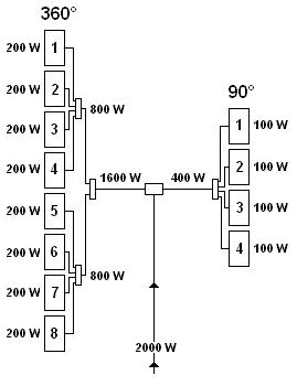
A radiating system can be composed of:
– A set of elementary antennas arranged one above the other at a suitable distance and all oriented in the same direction, in this case it has a curtain of antennas;
– From more curtains of antennas up to a number of four (90 ° -180 ° -270 ° -360 °) to form a solid with omnidirectional irradiation;
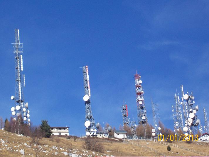
– From a single elementary antenna, such as occurs for the radio base stations for mobile telephony where each cell is a radiating system composed of a single elementary antenna that radiates in a certain direction. Figure 4 shows the radiation diagram of a system composed of two curtains of panels. Figure 5 shows some radiant systems in both television-type curtain panel in white, gray and red radio (guiding elements) related to the site of transmitter Castaldia in the municipality of Aviano (PN).

The spread of isofrequency SFN (Single Frequency Network)
An SFN network is a television transmission system that employs the same frequency in all the stations transmitting thanks to the technology of digital modulation COFDM (Coded Orthogonal Frequency Division Multiplexing). With this technology it is possible to compose positively isofrequency echoes that arrive at the receiver with a limited delay (window guard).
One of the many advantages of digital terrestrial broadcasting, in comparison with analogue, is to be able to transmit on the same channel by several different transmitting stations, also adjacent, without they interfere with each other. This is possible by making networks of digital broadcasting on single frequency SFN because the DVB-T system is immune to reflections enough to transmit the same bit at the same time and at the same frequency.
An example is that of the MUX MDS4 / MDS5 Mediaset and MUX2 / MUX3 RAI on the city of Rome, which transmit on the same channel UHF stations from different transmitting with the same service areas. These areas, if they were served with transmitters analogicim, would only produce quality images 1 that is unacceptable. In Figure 6 you can see a sketched SFN network with three stations transmitting on the same channel.

The key for achieving an SFN network is the accuracy and frequency stability of all the transmitters used to be synchronized to a single frequency reference. To achieve this, the satellite navigation system GPS (Global Positioning System) is used. This system provides a very precise temporal information to which it is possible to connect all the transmitters in the SFN network obtaining in this way a frequency precision of the order of 1 Hz.
The element most interested in the realization of SFN is the transport stream since all transmitters in the network must transmit exactly the same transport stream in a synchronized way.
For this reason, if you want to create an SFN network, you must set the MUX which must divide the stream in transpotr Megaframes with the addition of MIP (Megaframe Initialization Packet) in order to achieve synchronization by all transmitters in the network. In conclusion to realize an SFN network, you have perform the following phases:
- installation of a MUX with a GPS receiver and insertion of the MIP (Megaframe Inizializazion Packet);
- installation of a GPS receiver for the accuracy of the frequency of all the transmitters VHF or UHF;
- optimization of the network by regulating the time delay of the output transport stream of the transmitters to reduce the differences in the areas of interference;
- planning of the workstations, the powers in transmission and of the radiation patterns in such a way to minimize the areas of interference.
An SFN network to function properly it needs a good calibration of the powers in transmission, a transmitter of the network with power too high would be in condition to reach too far, and therefore, it would be to have a delay compared to another transmitter network closer, over the allowed limit.
This delay is called the GI (Guard Interval) and Italian networks SFN should not exceed 224 microseconds. In the case of areas with delays exceeding that range, you need to point your antenna to eliminate the signals delayed.
The ability to use the same channel for the same areas provides another important solution technique called Gap Filler. In practice, it represents the possibility to cover within a particular catchment area of a transmitter, all the small areas that are in shadow with respect to radioelectric transmitter itself, such as a small depression, behind a large building, inside tunnels or in small mountain valleys.
In practice, a Gap Filler is a small power repeater that receives and transmits the same main broadcasting channel. It can be considered as another part of the network SFN transmitter but without all the technical features necessary for large systems. The gap fillers avail themselves of the advantages to the reflected signals conferred on the OFDM modulation the guard interval.
Unfortunately, the gap filler has a big limit, that is, the isolation between the receiving antenna and the transmitting, as operating on the same channel, an excessive power in transmission would cause the self-oscillation of the transmitter. For this reason you need to install the antennas in order to achieve maximum insulation possible. The gap filter can only be used for small powers of a few watts.
The reception system
The system of receiving digital terrestrial television, with respect to a given catchment area, is basically composed of the following elements:
– aerial
It is the fundamental element of a reception system because as a result of a correct pointing, it must transform the energy of the electromagnetic field radiated by the transmitting into an electrical signal.
The main element that enables this transformation is the dipole (across which is connected to the coaxial cable that carries the signal of the input of any headend directly to the input of the decoder). It is produced in different shapes and along with elements such as reflectors and directors, it constitutes the antenna.
There are no specific aerials for analogue or digital signals or aerials for transmitting or receiving. The only choice you have to make reference to the following characteristics:
- frequency of use,
- gain,
- opening angle or radiation pattern,
- relationship forward / backward (ratio of sensitivity in the receive direction and in the opposite direction),
- input impedance (for television broadcasts and standardized to 75 Ω).
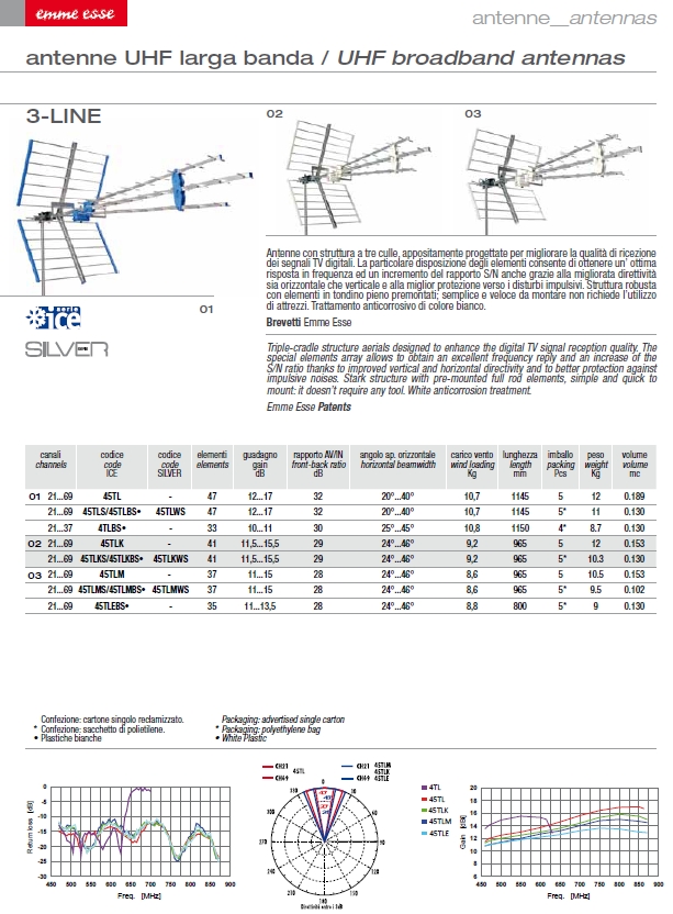
A particular type of aerial is the log-periodic which has the peculiarity of having a frequency band of very wide use, for example VHF and UHF from 45 to 860 MHz. On the other hand, it shows a low gain and little directivity. These characteristics make it suitable only for receiving in catchment areas with good field strength and the absence of reflections and noise.
Figure 7 shows the technical specifications and the radiation patterns of the log-periodic aerial models extracted from the catalog Fracarro #153. Figure 8 shows the technical specifications of the aerial 3-line extracted from the printed catalog of the Emme Esse (registration is required to download the catalog). Finally, Figure 9 shows the technical specifications of the aerial Sigma extracted from the catalog Fracarro #153


You should pay special attention while making the installation of the antenna, in a special way to support structures (poles, pylons, towers, etc.). In this regard, the CEI volume published in February 2013 (containing guides: 100-7 requirements for functionality and safety of facilities for receiving TV and 100-140 notions for the choice of the supports for antenna installations) recommended minimum distances between antennas in order to assess the length of the support for the verification of the resistant moment with respect to the bending moment, in order to use, or not, a bracing.
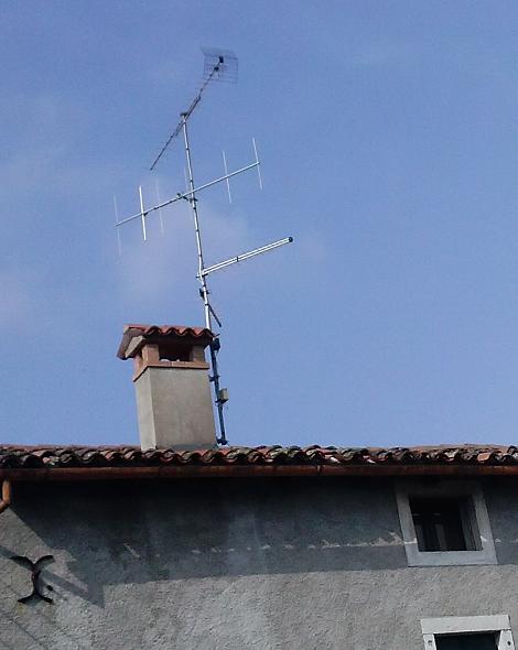
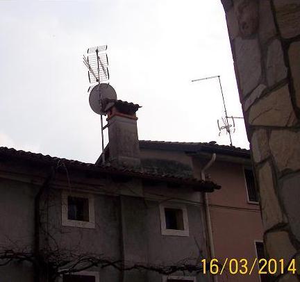
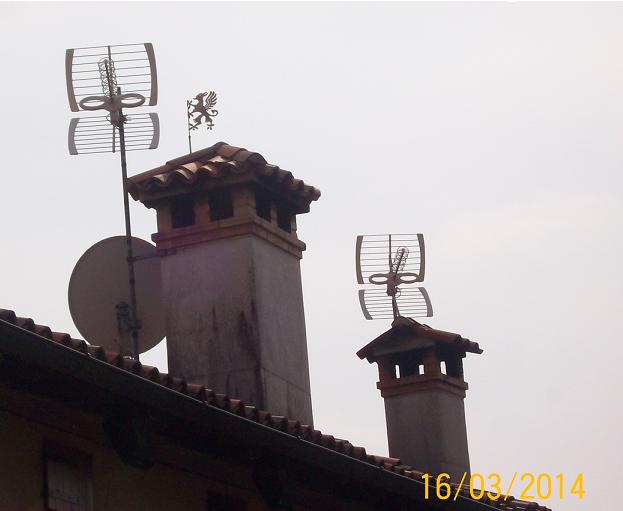
In many parts of Italy, it is customary to install the antennas with special brackets chimneys. This solution, while being very practical and fast, is not advisable because the deposit, in time, of residues and fumes can corrode the elements of the antenna, in particular the connection of the shielded cable to the dipole thus altering the characteristics of the antenna . In Figures 10 and 11 you can see some installations of antennas to chimneys.
– headend
It consists of all the equipment needed for a proper signal to distribute to users, includes attenuators, filters, mixers, demixer, channel converters, preamplifiers and amplifiers;
– distribution
The elements that belong to this category are:
- the shielded coaxial cable is used as a connection cable between the various elements that make up the reception system. it is characterized in that the impedance should be 75 Ω and by losses expressed in db for 100m;
- the divider is used to divide an incoming line in more drop lines such as the output line of the headend divided into two or more lines of the stairs of a building or areas of a villa. It is characterized by the number of outputs up to 8, the attenuation or loss of signal between the input and the output that will be higher the higher is the number of partitions, by decoupling, that is, by attenuation undergone by the signal passing from one output to another. If one or more outputs are not used, they must be strictly terminated with a resistance of 75 Ω;
- the shunt is used to allocate the user sockets, without interrupting the line, directly from the output of the headend or from the lines obtained with the use of the divider. It is characterized by an input and an output up to 8 derivations for user sockets, the loss of passage, attenuation of derivation and attenuation of decoupling;
- the user sockets can be of the type terminal or passing in this case must be respected the input and the signal output;
– decoder
It is the equipment which, if external, shall decode the signal coming from the TV by connecting it to your TV via the scart socket. If this equipment is instead built into the TV, you just have to connect the TV to the TV through an appropriate distribution of the coaxial cable.
Some devices for the reception of digital signals
Sometimes the reception of signals from distant stations transmitting over 60/70 km, even if SFN, it is very difficult.In these cases it is advisable to use high directivity antennas and report back / forward very high, in this way it is possible to discriminate the useful signals from those interfering. In the case in which the antenna characteristics are not sufficient, it is necessary to rotate slightly, thus reducing its overall gain.
This operation, in many cases, can be carried out only with the use of special and expensive instruments (field meter, spectrum analyzer) also in the “do it yourself” using service information (PSI progamme Specific Information) contained in the transport stream and displayed on the TV about the power and signal quality. it is sufficient to position itself below the antenna and connect it directly to the TV by turning or raising and lowering the antenna, making sure to focus on the quality of the signal with respect to power.
When receiving a digital television signal it is very important to shield the components, including antenna, by electromagnetic disturbances. An antenna in the wrong position, very old shielded cable or a cable with a shielding quality poor, an old amplifier or mixer with unshielded components in the air, a divider or shunt placed in junction boxes in contact with electrical wires crossed by strong currents, may be excellent antennas for receiving impulses that block the signal decoding resulting in no signal.
In conclusion, in the presence of problems in plants built before the transition to digital TV, it is much more convenient to undertake a total makeover reception system rather than undertake a costly search for any abnormalities. In the presence of extreme cases (strong disorder, the presence of excessive signal delay, signal strongly degraded, etc..) any possibility of improvement is entrusted solely to the quality of the antenna and its correct position, so as to guarantee the highest possible margin compared to threshold values.
In the DVB-T system, as in the analog system, the signal quality is evaluated according to five levels: Q4 and Q5 signal more than acceptable, Q3 reliable signal (this is also the limit of acceptability recommended), unreliable signal Q2, Q1 signal can not be decoded. In the analog system instead of level 5 is used to describe the perfect image while the level 1 to qualify the image unacceptable.The difference between these assessments of quality lies in the fact that in analog refers precisely to really like the image is viewed on the TV (increasingly degraded and with strong presence of snow). Instead, in digital, the image is always perfect while the evaluation is relative to its stability in time, that is why the plant of digital reception must be made to ensure a signal quality constant in time, as much as possible below the values threshold allowed.
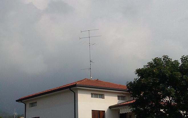
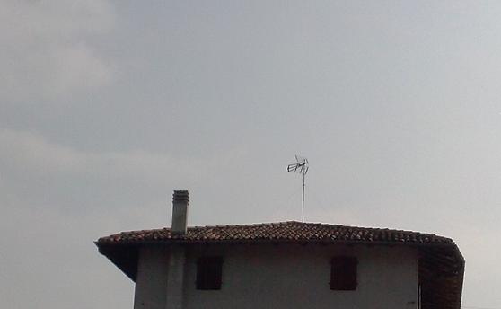
With the final introduction of DVB-T, the installations shown in Figure 12 and 13 shall be more and more rare. For reception of almost all the national television programs, and most important, the use of a single antenna will in fact be sufficient with obvious reduction of environmental pollution and greater security ( see Figure 14).