Introduction
Ardufonino is a mobile opensource created with Arduino, able to make and receive calls, and send and receive messages. In addition, with the implementation of this project, I wanted to lay the groundwork for the construction of a basic telephone system.
The idea came to me out of curiosity, because I wanted to do something that nobody had ever done, proving to everyone that want is power.
Ardufonino
Ardufonino consists of 3 party:
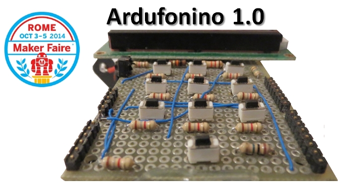
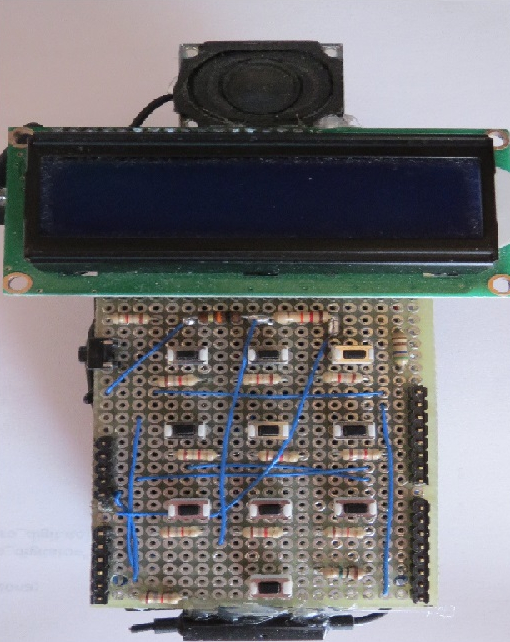
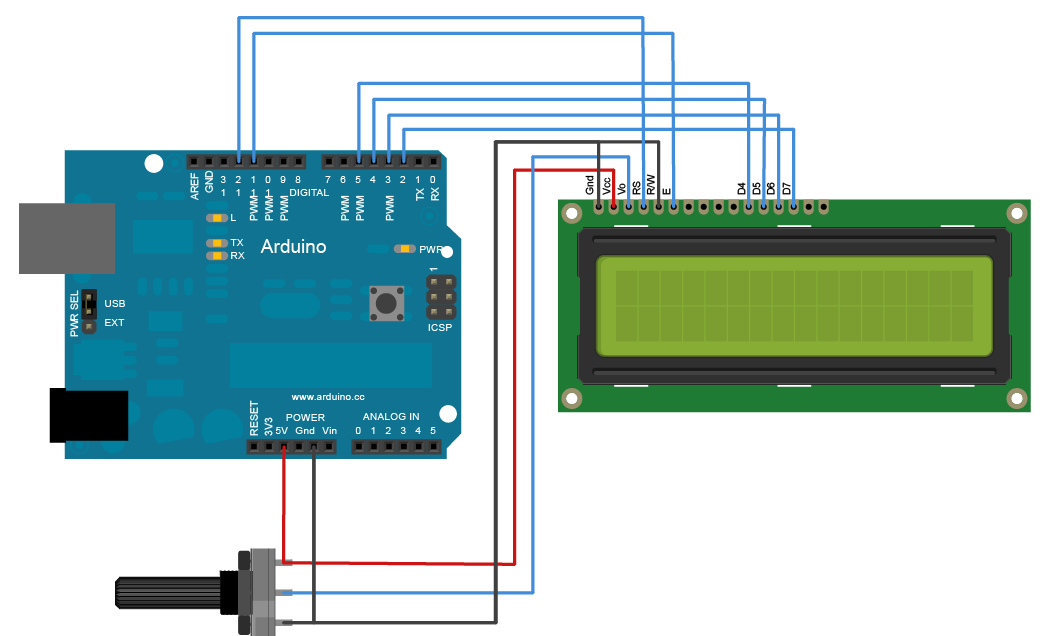
- Intefacing Shield, is the part with which we control the phone, is constituted by a keyboard 11 buttons, a LCD display Backlit, a microphone, a speaker, a trimmer and 13 resistors. The arrangement of the components is almost equal to that of the old phones with keyboard, because of its enormous comfort. In addition, this interface can be connected to either an Arduino UNO and an Arduino MEGA.
- GSM Shield, is a circuit that allows us to just send and receive calls and messages, to drive it will use AT comamnds to send Arduino via a serial communication. The antenna, a GSM module, audio output and input (through a connector jack) are embedded.

- Arduino UNO, a 16MHz microcontroller with 13 digital pins and 6 analog pins. It is the most important component of the project, because it allows the actual construction of the mobile phone, since it acts as an intermediary between the two shields.

For more information and download the software go to this link:
Power control
To view the battery level in the display I created the Livello_batteria( ) function, that allows us to see at the top right of the screen the status of the battery.
First, I created 9 arrays called: batteria_1, batteria_2, batteria_3, batteria_4, batteria_5, batteria_6, batteria_7, batteria_8 and simbolo_USB, each representing a charge level of the battery.
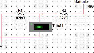
To be able to read the voltage of the battery I have used a voltage divider. This provides a voltage equal to half of the power to the analog pin.
The formula to do the calculation is very simple:
A1 = [ R2 / (R1 + R2) ] * Vcc
In our case we have:
A1 = [ 82000 / (82000 + 82000)]*9 = 4.5V
In order to know the voltage, you have to use this circuit, because the analog pin of Arduino can support up to 5V. Given that you need to connect 9 of these circuits, most likely you will burn the microcontroller.

Once I built the circuit, I completed the function, in which, I read the value of the voltage between 0 and 1023. By means a proportion (map), I converted this result in values between 0 and 8 (batteria variable). Then I assigned each of them to one of the previous arrays.

This function also allows us, to see if the phone is powered via USB, showing this icon, at the top right of the display. Knowing how much is 5V (more or less 530-541), I put an if statement, which makes this image only appear when i connect the USB.
Call
The program begins with a conversion of the call number from variable to string, allowing us, through the ATD command, to make the call. After that there will be a do loop with two tasks: to show the word “CALLING” on the LCD and to terminate the call with the ATH command, this only if we will push the button on the side of the phone.
Keyboard Control
In this project, the keyboard is essential, because it is the only way you can interface with the device (the alternative is to use the Serial Monitor)
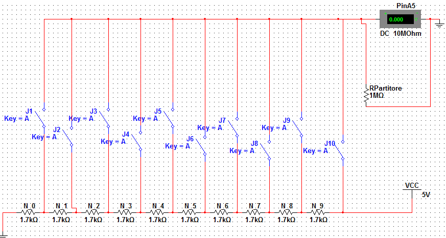
The image of the circuit diagram of the keyboard is shown above. This circuit allows us to read 10 buttons with only one analog pin. The operating logic is always that of the voltage divider, in fact, I do nothing more than assign to each resistance a value of 0.5V, and when a button is pressed it closes the contact, returning to the A5 pin a voltage equal to the number of resistors in the branch per 0.5. The resistance needed to do the partition is very large in order to avoid large losses.
Let’s assume that the J3 contact is closed, the voltage across the A5 ends will be equal to:
Rs = R0 + R1 + R2 = 5100 ohm
Vpuls = [ Rdivider/ (Rs + Rdivider)] * 0.5 * Nresistors =
Vpuls = [ 1000000/ (5100 + 1000000)] * 0.5 * 3 = 0.99 * 0.5 * 3 = 1.5V
Once you have made the circuit you go to write the program, that starts with a do loop, where you read the A5 pin every 10 mS. To exit, just press: or a key on the keyboard or the call key.
Then when you get out of the loop the analog value of the pressed button will be converted to the actual value of the key, using a proportion (map). Finally, the function will return this result.
The problem of the bounce was not solved via hardware, but software, by putting a delay within the function.
Inserting number
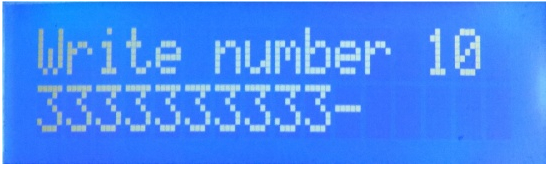
This function allows us to write, by means of the keypad, the number that we want to call. At the beginning, you can find the variables that will be incremented each time you type something, by sliding the next number to the right.
Subsequently you will find an if that, if it is true, will reset all variables, otherwise it will perform these two calculations:
numero_da_chiamare = numero_da_chiamare + ((numero_digitato) * potenza_posizione_numero);
potenza_posizione_numero = potenza_posizione_numero / 10;
translation:
call_number = call_number + ((dialed_number) * power_position_number);
power_position_number = power_position_number / 10;
The logic of the formula is very simple, for example, if we want to write following number
3286773254
the formula will be the following:
3*1000000000+2*100000000+8*10000000+6*1000000+7*100000+7*10000+3*1000+2*100+5*10+4*1 = 3286773254
Of course, the previous number will be added with the next one at every cycle.
Startup screen
This is the simplest function of the program, in fact, its job is to show some text while powering the phone, in order to give it time to connect to the network.
Reply & Call
This feature allows us to precisely respond to a call via the call button. This button, when pressed, will send the ATA command to the GSM, allowing us to respond. During the conversation, the program will execute a do loop that will display on the LCD display the message “CONVERSATION”. To end the conversation, just press the button on the side of the Ardufonino.
Page functions
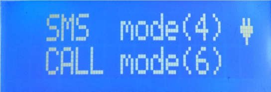
The Page functions show the possible actions to be taken on the LCD display, and which buttons to press.
Phonebooks
The cell phone numbers are stored in global unsigned long variables, and you can enter them using the keyboard.
In this program we have two types of phonebook:
- The phonebook reserved for calls: inside you find a variable that increases by 1 when the button 8 is pressed, and decrease by 1 if you press 2. This change will allow you to scroll through the phone numbers, which will be inside of a switch. Once you have chosen the number, just press the side button to make the call.
- The phonebook reserved for messages: This function is identical to the first, the only difference is that pressing the side button you send the message you choose.
I decided to make two phonebooks because having only one submit button I would have had trouble making a single function.
Sending messages
When this function is called, the GSM receives the AT + CMGS command. With this command, you can decide the number to which to send the message. Then the text (previously selected) is taken to be sent and by means of the line “mySerial.println ((char) 26;” is sent.
For convenience, I decided to include already loaded messages in the program, so I had to create a function for writing the message.
Reading messages
To read messages sent to you, just check if the serial interface of the GSM has outgoing available data, with the available function. If this is true, the function will show the message in the display.
Call button
The call button allows you to:
- call out
- reply
- send SMS
I decided to make it work in positive logic, that is:
- When it is pressed, it returns 1
- When it is not pressed, it returns 0
The reading of the button is performed by the digitalRead function on the digital pin 6.
Loop
In the loop cycle you find some if with the related else statements. These allow us to take advantage of all the features described above, using the keyboard.
References:
For more information and download the software go to this link: www.davidealoisi.it.