Introduction
This is the second part of the article published about a week ago that concerned the PIR motion sensors, explaining the technical details on their usage and operation (see here). In this article, continuing with the topic, you will see how to use them in a more practical way, or better, by using a Raspberry Pi board (in my case a Raspberry Pi Model B+).
Connetting PIR with Arduino
You will then begin, precisely from the point at which the previous article had been interrupted, that is, with the connection diagram realized with the Fritzing software. But this time, you will see a Raspberry Pi in place of the Arduino. So you have to build a circuit basing on the sketch below.
In the previous article you had seen that the color, the functionality and the arrangement of the three output cables may vary depending on the PIR model. So, before making any connections, it is important that controls the datasheet of the model in possession.
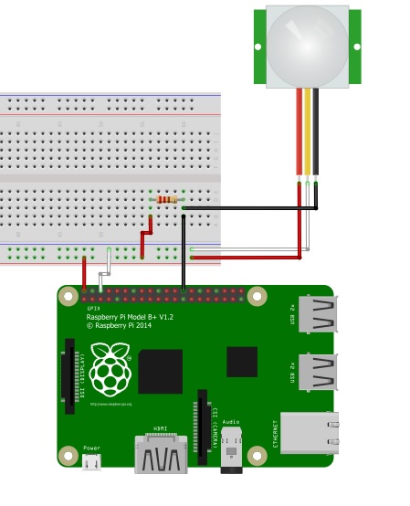
In the sketch above, I drew the connections basing on my PIR model, the SE-10. If your model should be different, and especially in the disposition of the cables, change the connections accordingly. The red wire is the +5V power supply, the white wire is the GROUND, and the black wire is the ALM which is the detection signal coming from the sensor. Moreover, you can notice a resistance in the sketcg, this must be 1kΩ.
In order to make all the connections between the PIR sensor and the GPIO pins in a right way, you will use a breadboard. Now, starting from the PIR sensor, give a look to the color of the three wires:
- connect the red wire to the positive rail (+) of the breadboard;
- connect the white wire to the negative rail (-) of the breadboard;
- connect the black wire to an empty rail in the middle of the breadboard.
Now, you have to take three other jumper, possibly with the corresponding colors.
- connect the negative rail (-) to the GPIO GND (pin 6) of the Raspberry, with a white jumper.
- connect the positive rail (+) to the GPIO 5V (pin 2) of the Rasbberry with a red jumper.
- connect the central rail (the rail with the black wire) to the GPIO 7 (pin 26) with a black jumper.
Insert a 1kΩ resistor in the breadboard in a way to connect the rail with the two black wires with a new empty rail. Finally this empty rail will be connected to the positive rail (5V) by another red jumper wire.
If you followed all the steps correctly, you get a circuit looking like the Frizing sketch. In my case, i build a circuit as shown in the following picture…

First example: print a message when a motions is detected.
Now, you have finished with the connections, you can start to develop the Python code. First, this code will activate the PIR sensor connected to the Raspberry. Then it will send you a signal everywhere it detects a movement through the ALM wire.
More precisely, first you have to set the GPIO pin 7 as input and then read the voltage (state) of this pin during the execution. There are only two possible states: LOW or HIGH. The HIGH state (3.3V) corresponds to when the PIR does not detect motion, the state LOW (0V) instead when motion is detected.
As first example, you will write a very simple script that shows when a motion is detected (or not) writing a message in the terminal. So, open a text editor and start to enter the code. For example, name the file pir01.py.
$ nano pir01.py
First, import the Python library necessary to work with the GPIO, called RPi.GPIO. Import the time module too, this will be useful in the code to set the time to wait between a reading and the next. Finally, set the numeration mode of the GPIO pins.
import RPi.GPIO as GPIO
import time

GPIO.setmode(GPIO.BCM)
Now, the next step is setting the GPIO 7 pin as input (this pin reads the HIGH and LOW state sent by the PIR sensor).
pirPin = 7
GPIO.setup(pirPin, GPIO.IN)
Before, it has been told that a you need to continuously read the status of the ALM wire, so you need to put the reading within a loop.
while True:
    if GPIO.input(pirPin) == GPIO.LOW
         print "Motion detected!"
    else:
         print "No motion"
    time.sleep(0.2)
When the ALM status is LOW, the condition is satisfied and then a “motion detected” message will be printed on the terminal. Instead if the state is HIGH, the condition is not satisfied and a message “no motion” will be printed instead.
This is the core of the program. Indeed, in more complex cases, i.e. your home experiments, you have to insert an action as response of a motion detection within the if condition. For example, you can take a picture of the room where a motion has been detected.
The complete code should look like as the following listing. In addition, I add a try-except construct in order to cleanly manage the quit of the execution everytime you click CTRL+Z. In this way, the pin status will be reset before to quit.
import RPi.GPIO as GPIO
import time

GPIO.setmode(GPIO.BCM)
pirPin = 7
GPIO.setup(pirPin, GPIO.IN)

try:
    while True:
        if GPIO.input(pirPin) == GPIO.LOW:
            print "Motion Detected!"
        else:
            print "No motion"
        time.sleep(0.2)
except KeyboardInterrupt:
    GPIO.cleanup()
Once you have entered the code, save the program in nano (CTRL+O) and then quit (CTRL+X). Then, through a SSH session, run the program with
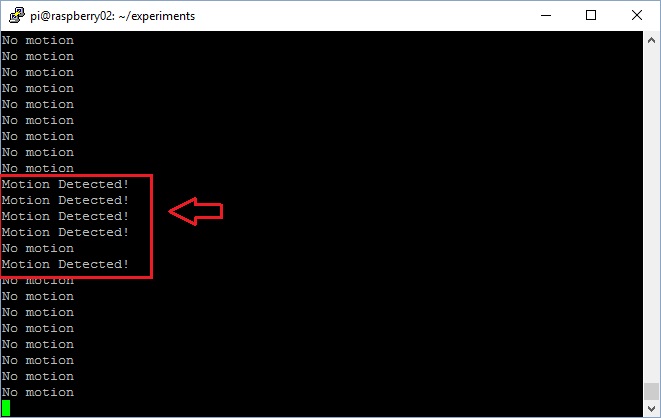
$ sudo python pir01.py
The program will print a “No motion” message repeatedly, but every time you will move the head o a hand next to the PIR sensor you will get the Motion Detected!” message.