In this post we will see how to make a laser barrier to integrate with an Arduino board.
The applications of a light barrier (laser and infrared) are numerous, especially whenever we want that the passage of a person or of an object through a threshold triggers a certain event. This event may be, for example, a count if what we need is to count the number of objects that cross a threshold (on a conveyor belt for istance). Another example would be taking a photo at the precise moment an animal crosses the space delimited by the laser (photo hunting). Or again, it is the activation of an audible and / or visual alarm to protect a specific area that you want to control access. If you place two or more laser barriers in sequence you can measure the elapsed time between the two thresholds, and then measure in some way the speed of an object or a person.
Browsing around the net i wanted to find a starting point from which to begin. So i found an article written by M.Ribble www.glacialwanderer.com/hobbyrobotics. In this article a laser barrier for photo hunting is presented.
Since my needs are different and i want to especially develop something which is the more general possible, i make some changes to the laser barrier discussed in that article. In fact, i need to split the circuit in two separate parts: an emitter (the LED laser) and a receiver (photoresistor). These two modules will be connected to the Arduino board and managed separately. Making two separate modules, independent of each other, expands the application possibilities. So we can include them in any project and mount on any infrastructure, adapting them to different situations each time.
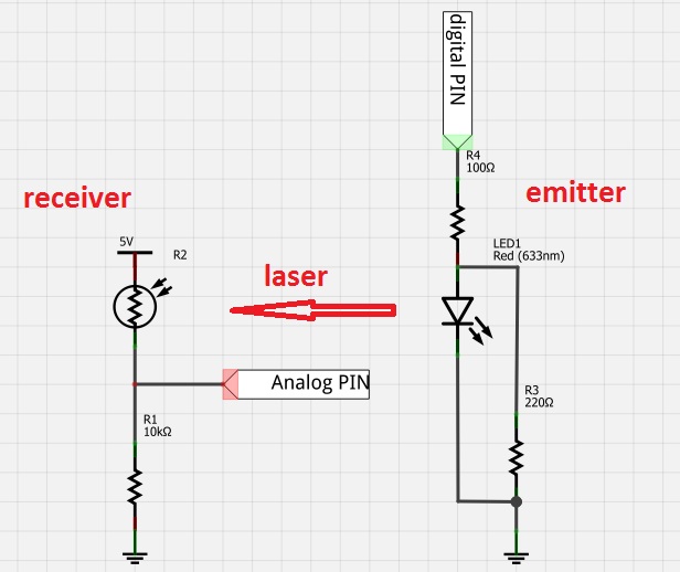
Fig.1 shows the circuit diagram of the two modules.
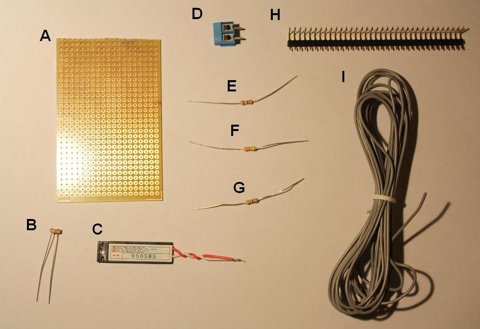
First, the following is a list of all the necessary shown to make our barrier laser in Fig.2
- A) a stripboard
- B) a photoresistor
- C) a red laser LED
- D) a 2-channel screw terminal
- E) a 100Ω resistor
- F) a 10kΩ resistor
- G) a 220Ω resistor
- H) a male bent connectors strip
- I) an electric wire
While the rest of the material is easily purchased at any electronics store, as regards the laser led, I found this product on the Sparkfun site:
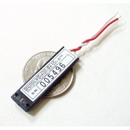
Laser card Module – Red ( Sparkfun COM-00594 )
Maker: Wenta Electronics co., LTD, China
Wavelength: 650nm (645-660nm)
Output power: 0.45 to 0.80mW
Input power source: 3.1V+/-10%
Consumption current: 35mA (max 40mA)
Laser spot: circle
Laser life: 3000 hours
In Fig. 3 the receiver board is shown. You can notice that I bent the photoresistor so that it laterally faces toward the opposite side with respect to the three pins.
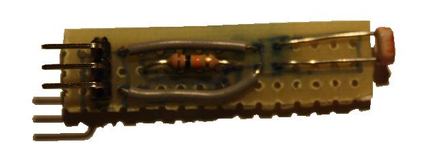
Fig.3: receiver board with the photoresistor
In Fig.4 the emitter board is shown. The screw terminal is soldered on the opposite side with respect to the 2 pins. In this way the lase LED could be easily removed and replaced from the board.
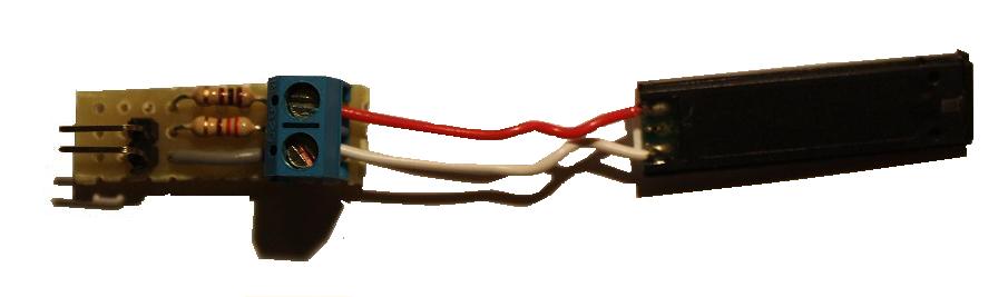
Fig.4: emitter board with the laser LED
Now that we have the two modules, we can connect them to the Arduino board ( Arduino UNO in my case).
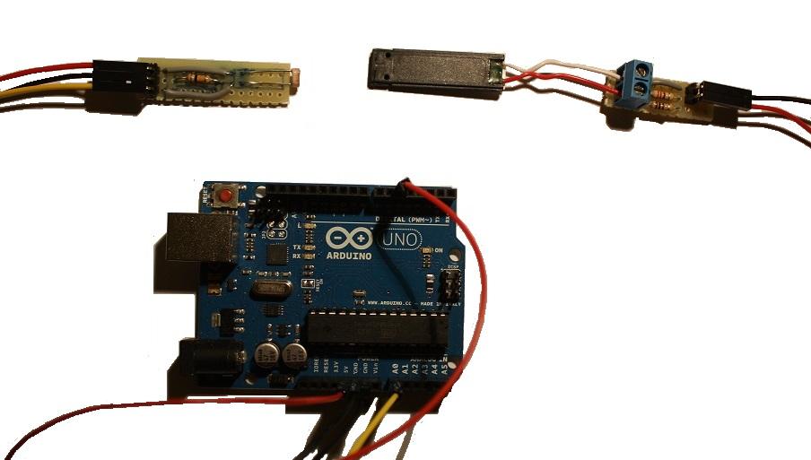
Fig.4: emitter and receiver boards connected to an Arduino UNO board
This is the configuration of the connections between the Arduino board and the two modules. The pin labes are reported consistently with the following code example.
- PIN D5 —-> laser emitter
- PIN A0 —-> receiver signal
- 5VDC —-> receiver power supply
- GND —> emitter and receiver ground
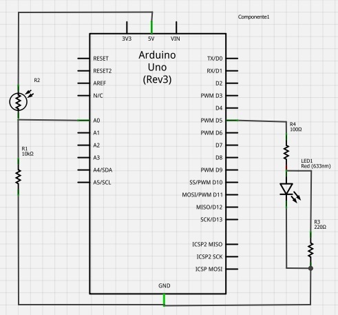
Fig.5: circuit diagram of the laser barrier on Arduino
And here is the code for the laser trigger:
 #define LASER_PIN 5
 #define LASER_THRESHOLD 600
 #define LASER_TRIGGER_ANALOG_PIN 0

int laserVal;

void setup()
 {
 pinMode(LASER_PIN,OUTPUT);
 digitalWrite(LASER_PIN,LOW);
 digitalWrite(LASER_PIN,HIGH); //turn on the laser
 Serial.begin(9600);
 }

void loop()
 {
 laserVal = analogRead(LASER_TRIGGER_ANALOG_PIN);
 delay(1000);
 //Serial.println(laserVal);
 if(laserVal < LASER_THRESHOLD)
 {
    digitalWrite(LASER_PIN,LOW); //turn off the laser
    //Scrivi qui il codice che viene eseguito quando il fascio viene interrotto
    delay(100);
    digitalWrite(LASER_PIN,HIGH); //turn on the laser
 }
 }
Once we have compiled the code and the loaded on the Arduino board, we need to adjust the threshold value (LASER_THRESHOLD) depending on the type of led laser and the brightness of the environment. A good compromise is an average value of 600. The receiver continuously sends a value (laserVal) to the Arduino board. This value is proportional to the brightness detected by the photoresistor. The greater the value, the greater the brightness detected. Therefore, while Arduino is receiving laserVal values greater than the threshold value, the laser barrier is considered as not interrupted. At the precise moment in which Arduino receives a lesser value than the specified LASER_THRESHOLD, the if condition within the loop() function is met and the inner code will be executed. The laser will be temporarely turned off (100 milliseconds) and the turned on again. This is possible because the power supply for the lase LED comes from the PIN 5 and not from the 5VDC pin on the Arduino board. This choice allows us to control the switching on and off at will.[:]