Servo motors are a particular type of motor, which thanks to their characteristics and ease of use, are often used in the first examples of motor control on boards such as Arduino or Raspberry. Model making makes a lot of use of this type of motors and there are many low-cost servo motors available on the market, also useful for educational purposes. In this article we will first see what servo motors are, how to use them and finally how to program Arduino in order to use them with some simple examples.
What is a Servo Motor
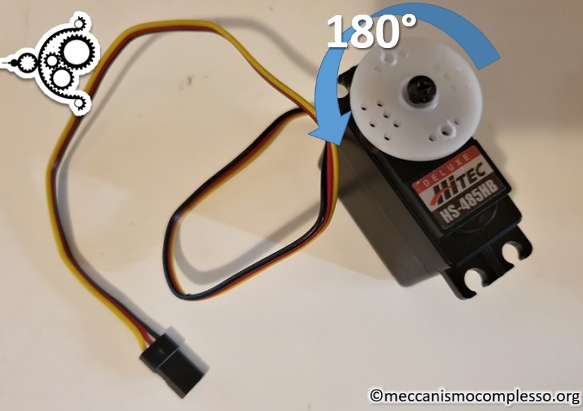
A servo motor has the peculiarity of setting the rotation transmission pin on exact angles included in a certain range, which often go from 0 to 180 °, but there are also models that cover greater ranges.
Having a motor that adjusts the rotation of an axis to make it assume a precise desired angle is useful in many applications. Just think of simple modeling, in which we want to use this motor to adjust the rotation of a rudder for a ship or an airplane, or that of a steering wheel to turn the wheels at a certain angle.
Other possible applications can be those in robotics, when you want to make certain components assume particular angles with each other.
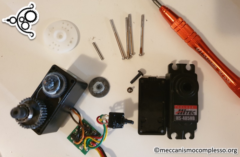
To achieve this particular movement, one must analyze in detail how a servo motor is composed inside. The rotation of the output pin is obtained through a DC motor (direct current) connected to a reduction mechanism that allows to increase the torque during the rotation phase, reducing the speed and increasing the torsion force.

As for the control of the rotation angle, this is implemented through an internal control circuit which, thanks to a resistive potentiometer, is able to know the rotation angle of the pin. Once the desired angle is reached, the control circuit blocks the motor.
Thanks to this mechanism, the servo motors are able to guarantee very precise control over the degree of rotation of its pin.
How servo motors work
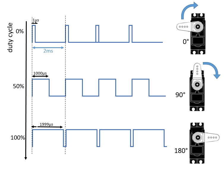
A servo motor controls the rotation of a DC motor through a control circuit that adjusts its angle. Control is achieved by adjusting the length of a square wave pulse sent to the servo motor. The length of the pulse in a train of signals is defined by the Pulse Modulation Width (PMW).
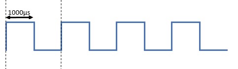
This train of pulses is characterized by the duty cycle, that is the time occupied by the pulse with respect to the period destined for a single signal. For example, the classic square wave has a duty cycle of 50%, since the duration of the pulse (part of the signal with state 1) is equal to half the period of the wave (i.e. equal to that part of the signal with state 0 ).
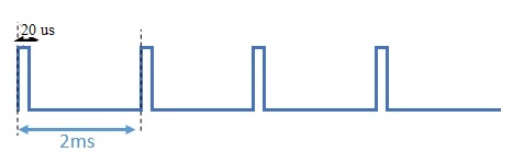
But you can have other pulse trains with different duty cycles. In fact, if we reduce the duration of the signal state 1, we will reduce the duty cycle.
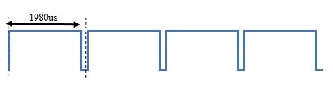
Or you can do the opposite, by increasing the period, to obtain higher duty cycles.
By then modulating these durations while sending a pulse train, information can be sent to the control system in the servo motor. Depending on the duty cycle, the angle of rotation will vary. Starting from a duty cycle of 1%, corresponding to the angle of 0 °, as the duty cycle gradually increases, the angle of rotation of the servo motor will also increase. With a 50% duty cycle, the motor pin will position itself at 90 ° (which is just half of the possible rotation range). With a duty cycle of 99%, we will have a rotation of 180 °.
Then, through this PMW modulation system, we will be able to send commands from the outside to the servo motor to make it assume the desired angle of rotation.
Arduino and PMW
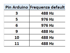
Arduino è in grado di generare dei PMW in maniera molto semplice. Per quanto riguarda i vari PIN, si possono avere due diverse frequenze di emissione di PMW.
To use servo motors in a simple and intuitive way, and generate the PMW with the desired duty cycle, Arduino IDE includes a specific library, called Servo. To be able to include it in the sketch, just add it at the beginning.
#include <Servo.h>
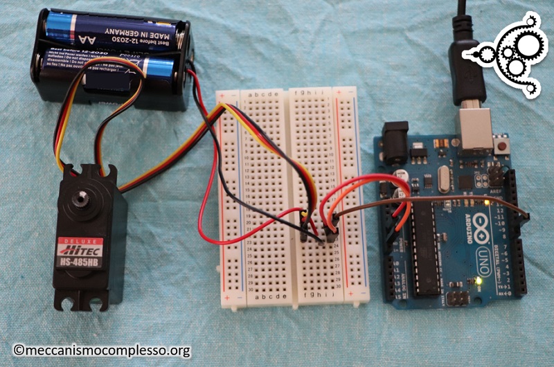
Assembling Arduino with the servo motor
Many of the commercially available modeling servo motors run on 5V, and therefore can connect directly to the 5V PIN power supplied by Arduino. But to ensure greater security of the card (and the USB port connected to the computer) it would be better to add an external power supply.
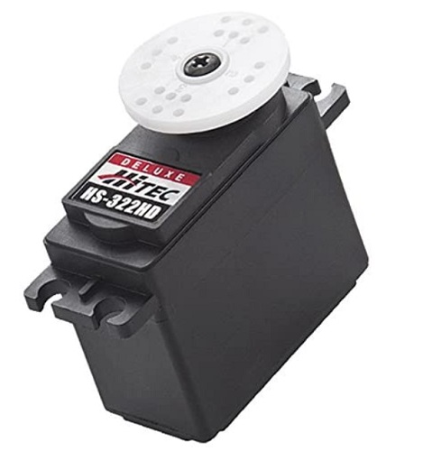
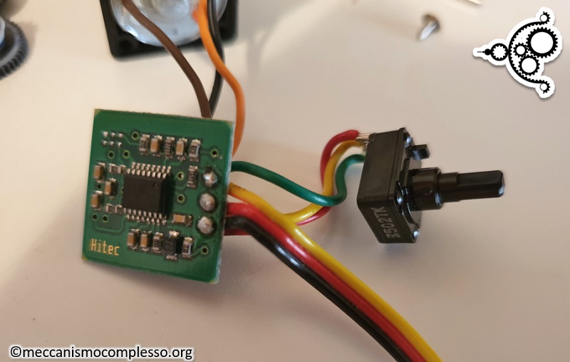
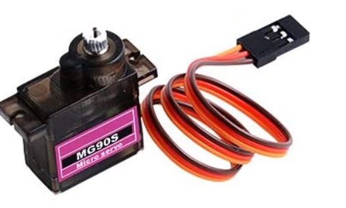
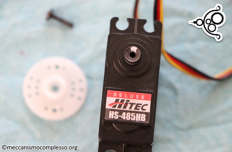
In my example I used a Hi-Tec SERVO HS-485HB servo motor, but any other type of 5V modeling servo motor, such as Hi-Tec SERVO-322HD or micro servo motors like MG90S or SG90S, is fine.
So in my case I preferred to add a 4 AA battery compartment module as a power source.
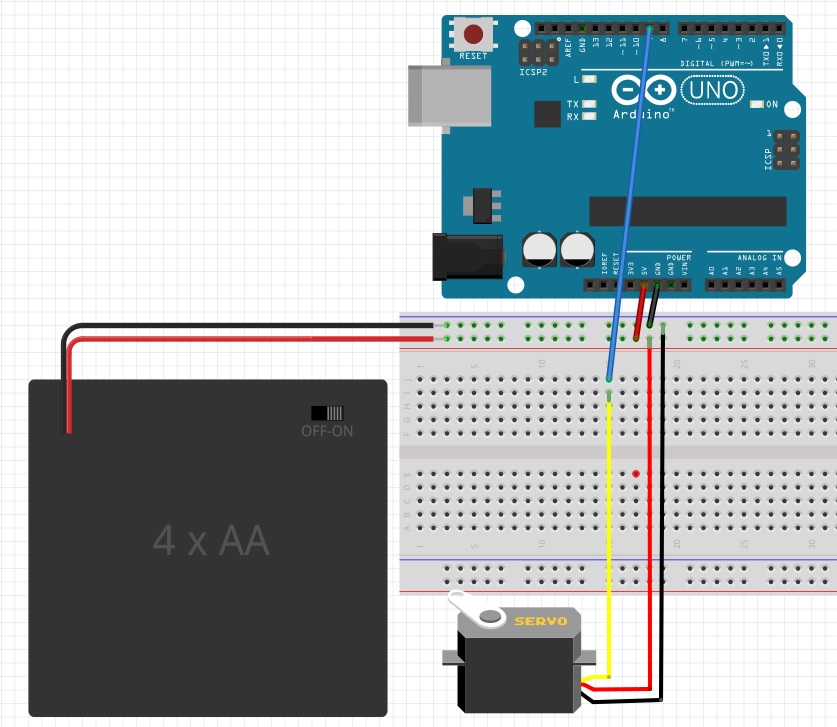
As you can see, I connected the Arduino PIN 5V and the GND PIN to the external power supply, this allows us to power the Arduino board as well as the servo motor. In fact, once you have downloaded the sketch compiled on the Arduino board, you can disconnect the USB port, and the Arduino will continue to work powered by batteries.
But be careful, it is a particular and rather risky connection for the Arduino board, if you do not understand what you are doing and do not follow particular precautions. In this regard, I add an in-depth paragraph on the matter.
Power supply with direct connection to Pin 5V
It is possible to connect a stabilized voltage directly to the Arduino 5V PIN in order to power it (together with the ground on the GND PIN). The applied voltage must be absolutely between 4.5V and 5.5V. Since there is no type of protection, any higher value would lead to irreversible burning of the board. A voltage lower than its malfunction. Even the accidental inversion of the cables, between positive and negative, would lead to the destruction of the board.
A positive aspect is instead that of no longer having to keep the voltage regulator under control for any overheating, since it is no longer used.
So as in the case in question, when you need to work with additional devices that require 5V, this connection could be ideal, such as servo motors.
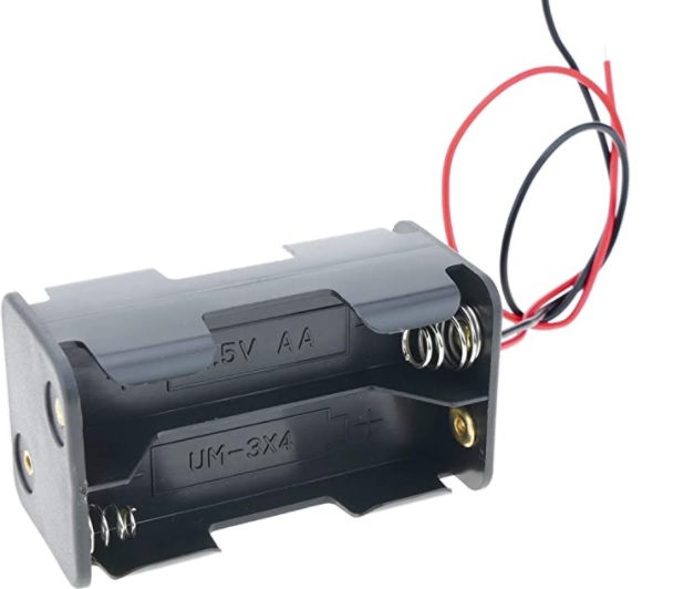
As far as the power source is concerned, the best solution is to use a module with 4 batteries, rechargeable in series, each of which has a nominal voltage of 1.25V, and therefore can generate a voltage of 5.0V. Pay attention instead to normal AA batteries (which should have a nominal voltage of 1.5V). In fact, the latter provide voltages equal to 6V, too high voltage to be supported by Arduino.
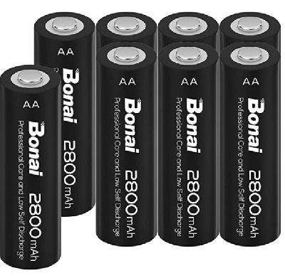
Therefore, the solution is to use only KR6 (NiCd) or HR6 (NiMH) Rechargeable Stylus Batteries. If you are unsure, before using batteries in series, measure their voltage with a voltmeter.
Programming Arduino
Now, once all the connections have been made, let’s open the Arduino IDE and start writing two simple examples, which will allow us to understand the basic commands of the Servo library, and see how the servo motors work.
Define the angle at 0 °
First it would be useful to be able to mark in some way the position of the pin corresponding to 0 °. This is very useful to then screw the white perforated discs into the right position and thus adjust accordingly to the possible set-up of the movement space between 0 and 180 °.
So let’s make a sketch that sets the servo motor on the position corresponding to the rotation at 0 °.
Let’s open Arduino IDE and insert the following sketch.
The first line of code imports the library which provides us with a series of methods and functions that make it easier for us to control one or more servo motors. Once the library has been imported, the first thing to do is to create an object corresponding to the servo motor that we will use throughout the code. In fact, you can use different servo motors and specify each of them uniquely. So we’ll call servo1 the servo motor in our example.
Inside the setup() block of the sketch, we will insert the attach() function which will define on which pin the servo motor, servoPin, is connected.
servo1.attach(servoPin);
In the loop() block instead we will insert the write() function, again referring to our servo1 motor.
servo1.write(angle);
The angle specified as a parameter should be expressed in degrees with a range from 0 to 180 degrees. The specified angle modulates the duration of the pulse sent to the servo motor via PMW. The latter will move to the corresponding position. So to make the pin turn to the 0 ° position, we write:
servo1.write(0);
We compile and upload the sketch on Arduino. The servo motor will move to the position corresponding to 0 °. At this point, mark the reference position with a white marker. From this point on you can assemble and disassemble the perforated discs, and other accessories using this sign as a reference point.
Moving the Servo motor over the entire range of angles from 0 to 180 degrees
Now that we have seen the essential functions to send angles to the servo motor on which to position, let’s see a slightly more complete example, in which we will rotate the servo motor gradually covering the whole rotation range.
Copy the following sketch on Arduino IDE
We put a FOR loop in the loop () block, so it iterates between 0 and 180 degrees gradually, degree by degree. The write () command will shift the servo motor one degree for each iteration. At the end of the cycle, the servo motor will reach 180 ° and then restart from 0 °.
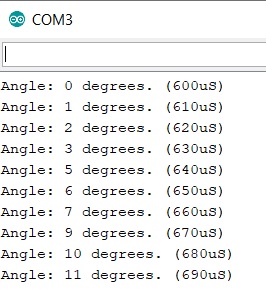
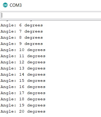
Compared to the previous example, we have created a serial communication in order to monitor the progress of the motor rotation, sending the current position angle of the servo motor to the Arduino IDE Serial Monitor.
Compiling and uploading the sketch on Arduino, and after starting the Serial Monitor we will see the servo motor move very very slowly, almost imperceptibly. On the monitor, however, all the current positions of the servo motor will be displayed in real time.
The SERVO.writeMicroseconds() method
The servo.write(angle) command works for most but not all servo motors. Some servo motors have a range of 180 degrees, others a range of 90 degrees, and some somewhere in between. Using the servo.write(angle) command allows a maximum of 180 steps. However, there is a command that allows up to 1000 steps: servo.writeMicroseconds(). For most applications, the simple servo.write (angle) will work fine. But if you want finer control, you’ll need to use servo.writeMicroseconds().
We then modify the previous sketch code to be able to use this function. By checking the specifications of the servo motor used and knowing that the PMW frequency of PIN 9 on Arduino is 488Hz. We will have a pulse train with a period of 2000 us. In this case we will no longer have the translation in degrees angle, and therefore we will have to carry out several tests to calibrate the length in microseconds of the pulses with the rotation angle.
This example, thanks to the pin of the servo motor marked at 0 °, to be able to somehow translate the duration of the pulse (or percentage of the duty cycle) with the rotation angle of our servo motor (this will change from model to model) .
In my case I made my servo motor rotate starting from 600 us up to the maximum value of 2000 us, which on Arduino is equivalent to a duty cycle of 100%. To increase the speed I made iterate in the FOR loop, the times at 10 us per iteration.
for(int i=60; i < 200; i++ ){
int t = i*10;
Also in this case, I will use the serial monitor to follow the rotation trend and see (and rectify) the value of the degrees corresponding to the various pulse durations.