
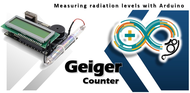
Going back to the old boards that I found in a box, I found this Geiger counter perfectly functional to be interfaced as a shield to Arduino. In this article we will see its features together, and at the same time better understanding what a Geiger counter, or radiation sensor, is and how it works.
The shield board of Libelium
The shield board to be interfaced to Arduino is distributed by Libelium. The structure of the card is divided into two different parts:
- signal circuit
- power circuit
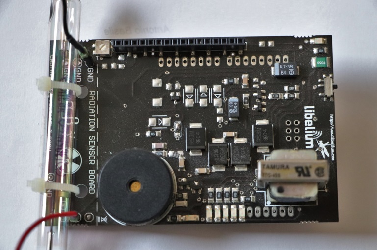
The part dedicated to the power circuit is able to provide a high voltage (400V-1000V) absolutely necessary for the operation of the Geiger tube. To obtain such a high voltage, several Zener diodes connected in series are used.
The part dedicated to the signal circuit has the task of receiving the impulses coming out of the Geiger tube, adapting them and sending them to the microcontroller which will in turn have the task of counting them.
Arduino’s task
Once connected to the board, Arduino must be programmed in order to receive the signals received by the Geiger counter, count them and produce a measurement that can then be used to evaluate the degree of radioactivity present in the measurement site.
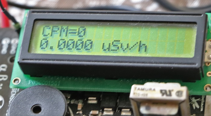
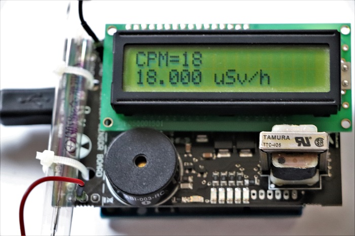
The impulses will be collected for a period of 10 seconds, which will then be multiplied by 6 in order to simulate the number of impulses per minute (cpm – counts per minute). Once this value is obtained, the cpm will be divided by a unique conversion factor for each type of Geiger tube used. This value can be found on the datasheets supplied by the manufacturer of the Geiger tube. We will thus obtain the value of the radiation which is measured in µSV / h (micro Sievert per hour) by means of the following calculation.
cpm * conversion factor = μSv/h
LCD Screen
A liquid crystal screen (LCD screen) is supplied with the shield card to which it will be connected via a 4bit line (4 data lines, in addition to the RS, Enable and RW control lines). On this screen we will display the CPM values and the reading of the radiation present in µSV / h.
What is a Geiger tube and how it works
But the real heart of it all is the Geiger-Muller tube connected to one side of the board. This glass (or even metal) tube is filled with an inert gas such as helium, neon or argon and brought to low pressures (about 0.1 atm). Inside the tube there are two electrodes between which a potential difference of several hundred volts is placed. One of the electrodes is made up of a wire that passes through the center of the tube (anode), while the other electrode is made up of the internal surface of the tube, often covered with a conductive material (cathode). The internal structure of the tube is created so as not to allow any flow of current.
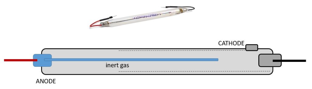
The radiation present in the environment passes through the surface of the tube and thanks to its ionizing power, some molecules or atoms of the inert gas are ionized creating positively charged ions and electrons. The large difference in potential between the two electrodes constitutes a very strong magnetic field which accelerates the ions towards one of the electrodes (depending on its charge). Along the way, the ions collide with other molecules, ionizing them in turn, creating a cascade of ions. This flow in contact with the electrodes will produce a current pulse which will be detected by the board and then transformed into a count.
The Geiger tube used for this particular shield is the J305ß model, designed to be sensitive to both beta and gamma radiation. It is also chosen precisely for its low price and its small size (11 cm in length). To calculate the radioactivity value, the conversion factor is 0.008120.
Other components on the shield board
We all know the geiger counters from TV, which can be recognized by that crackle that indicates the counts made. The higher the rattle, the higher the level of radiation detected by the environment. To obtain this sound, a Piezo speaker has been inserted on the board which will emit a sound for each pulse detected, regardless of Arduino control.
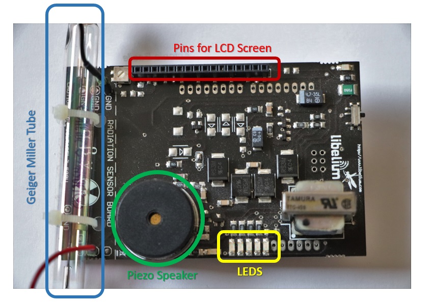
In addition, there is always a LED bar on the board consisting of 5 standard LEDs, 3 green and 2 red. These LEDs are controlled directly by Arduino to which they are connected by a series of resistors. Here is the scheme:
| LED green 0 | PIN 9 digital |
| LED green 1 | PIN 13 digital |
| LED green 2 | PIN 12 digital |
| LED red 0 | PIN 11 digital |
| LED red 1 | PIN 10 digital |
There is also a switch on the edge of the shield board with two ON and OFF positions.
Types of radiation
Alpha rays
Alpha radiation consists of positively charged particles (+2) emitted directly from the nucleus of a decaying radioactive atom. These particles are very dense and heavy and therefore are able to propagate in the environment for only a few centimeters (in the presence of air) and they cannot overcome even the simplest barriers. Generally this type of radiation is not very worrying, as long as the radioactive substance that generates them is not ingested or injected into the human body.
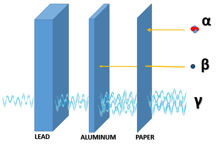
Beta rays
Beta radiation consists of negatively charged particles (-1) emitted by a decaying radioactive atom. These particles are smaller and lighter and are able to penetrate a few millimeters inside metals. They are therefore very harmful to the living tissues to which they are exposed.
Gamma rays
Gamma radiation represents the highest energy part of the electromagnetic spectrum (the same as radio waves, the visible, infrared, etc.). These high energy rays are capable of penetrating anything. Only heavier and denser metals are able to shield or at least attenuate them, such as lead. Gamma rays are naturally produced by the sun to arrive on the earth’s crust as “cosmic rays”. This radiation is very dangerous.

Environmental radiation
We have seen how radiation can arrive in our atmosphere in the form of cosmic rays. But this is not the only form of natural radiation to which we are subjected daily. In fact, there are many radioactive materials in the soil that produce one of the three types of radiation seen previously, during the decay process of atoms. The radioactive minerals best known to all are those based on Uranium, but there are many other elements, and radioactive isotopes present in the minerals of the earth’s crust.

We are therefore always subjected to background radiation. This will vary according to our geographical area, altitude and many other factors. Common background or ambient radiation ranges from about 3650 – 7200 μSv per year.
But what are the values that can produce health problems? First of all, it is important to specify that it is necessary to take into account not only the intensity of the radiation, but above all the time of exposure to it. For this reason it has been established that the limit value of radiation absorbed in a year must be less than 50000 μSv (about 10 times higher than the level of environmental radiation). So if not exposed to radioactive substances, we have nothing to worry about. Consider that an X-ray plate does not exceed 100μSv.
Connect it all together
Take the cathode tube supplied and solder the two connectors at the ends to the two empty perforated positions on the board. Once well welded, secure the Geiger tube to the board with two clamps to keep it locked. In this regard there are two holes in correspondence on the shield card.
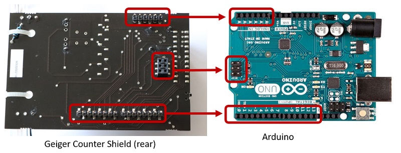
The Arduino board will act as a base for the shield (Radiation board) which will be inserted occupying almost all the pins. To power the entire Geiger counter, simply use the 5V pin on the Arduino. While the pulses output from the card will be received as interrupt 0 on digital PIN 2. Then above the shield we insert the card with the integrated LCD screen, using the pins already set in the upper side.
Source Code for sketch
Here is the source code:
 /*
  *  ------Geiger Tube board (Arduino Code) Example--------
  *
  *  Explanation: This example shows how to get the signal from the Geiger Tube
  *  in Arduino, we use one of the Arduino interrupt pins (PIN2).
  *  We count the time (ms) between two pulses of the Geiger tube.
  *
  *  Copyright (C) 2011 Libelium Comunicaciones Distribuidas S.L.
  *  http://www.libelium.com
  *
  *  This program is free software: you can redistribute it and/or modify
  *  it under the terms of the GNU General Public License as published by
  *  the Free Software Foundation, either version 2 of the License, or
  *  (at your option) any later version.
  *
  *  This program is distributed in the hope that it will be useful,
  *  but WITHOUT ANY WARRANTY; without even the implied warranty of
  *  MERCHANTABILITY or FITNESS FOR A PARTICULAR PURPOSE.  See the
  *  GNU General Public License for more details.
  *
  *  You should have received a copy of the GNU General Public License
  *  along with this program.  If not, see <http://www.gnu.org/licenses/>.
  *
  *  Version:          0.3
  *  Design:           Marcos Yarza, David Gascon
  *  Implementation:   Marcos Yarza
  */

 // include the library code:
 #include <LiquidCrystal.h>

 // initialize the library with the numbers of the interface pins
 LiquidCrystal lcd(3,4,5,6,7,8);


 // Threshold values for the led bar
 #define TH1 45
 #define TH2 95
 #define TH3 200
 #define TH4 400
 #define TH5 600

 // Conversion factor - CPM to uSV/h
 #define CONV_FACTOR 0.00812

 // Variables
 int ledArray [] = {10,11,12,13,9};
 int geiger_input = 2;
 long count = 0;
 long countPerMinute = 0;
 long timePrevious = 0;
 long timePreviousMeassure = 0;
 long time = 0;
 long countPrevious = 0;
 float radiationValue = 0.0;

 void setup(){
   pinMode(geiger_input, INPUT);
   digitalWrite(geiger_input,HIGH);
   for (int i=0;i<5;i++){
     pinMode(ledArray[i],OUTPUT);
   }

   Serial.begin(19200);

   //set up the LCD\'s number of columns and rows:
   lcd.begin(16, 2);
   lcd.clear();
   lcd.setCursor(0, 0);
   lcd.print("Radiation Sensor");
   lcd.setCursor(0,1);
   lcd.print("Board - Arduino");
   delay(1000);

   lcd.clear();
   lcd.setCursor(0, 0);
   lcd.print(" Cooking Hacks");
   delay(1000);

   lcd.clear();
   lcd.setCursor(0,1);
   lcd.print("www.cooking-hacks.com");
   delay(500);
   for (int i=0;i<5;i++){
     delay(200);
     lcd.scrollDisplayLeft();
   }
   delay(500);

   lcd.clear();
   lcd.setCursor(0, 0);
   lcd.print("  - Libelium -");
   lcd.setCursor(0,1);
   lcd.print("www.libelium.com");
   delay(1000);

   lcd.clear();
   lcd.setCursor(0, 0);
   lcd.print("CPM=");
   lcd.setCursor(4,0);
   lcd.print(6*count);
   lcd.setCursor(0,1);
   lcd.print(radiationValue);

   attachInterrupt(0,countPulse,FALLING);
 }

 void loop(){
   if (millis()-timePreviousMeassure > 10000){
     countPerMinute = 6*count;
     radiationValue = countPerMinute * CONV_FACTOR;
     timePreviousMeassure = millis();
     Serial.print("cpm = ");
     Serial.print(countPerMinute,DEC);
     Serial.print(" - ");
     Serial.print("uSv/h = ");
     Serial.println(radiationValue,4);
     lcd.clear();
     lcd.setCursor(0, 0);
     lcd.print("CPM=");
     lcd.setCursor(4,0);
     lcd.print(countPerMinute);
     lcd.setCursor(0,1);
     lcd.print(radiationValue,4);
     lcd.setCursor(6,1);
     lcd.print(" uSv/h");

     //led var setting
     if(countPerMinute <= TH1) ledVar(0);
     if((countPerMinute <= TH2)&&(countPerMinute>TH1)) ledVar(1);
     if((countPerMinute <= TH3)&&(countPerMinute>TH2)) ledVar(2);
     if((countPerMinute <= TH4)&&(countPerMinute>TH3)) ledVar(3);
     if((countPerMinute <= TH5)&&(countPerMinute>TH4)) ledVar(4);
     if(countPerMinute>TH5) ledVar(5);

     count = 0;
   }
 }

 void countPulse(){
   detachInterrupt(0);
   count++;
   while(digitalRead(2)==0){
   }
   attachInterrupt(0,countPulse,FALLING);
 }

 void ledVar(int value){
   if (value > 0){
     for(int i=0;i<=value;i++){
       digitalWrite(ledArray[i],HIGH);
     }
     for(int i=5;i>value;i--){
       digitalWrite(ledArray[i],LOW);
     }
   }
   else {
     for(int i=5;i>=0;i--){
       digitalWrite(ledArray[i],LOW);
     }
   }
 }