Introduzione
LilyPad Arduino is one of the many Arduino microcontrollers, but unlike the more well-known Arduino UNO, MEGA and Yun, this little board has very specific characteristics that make it unique. In fact, the LilyPad can be sewn on fabric. In fact, with less than 5€ you can add technology to our garments, but also bags, shoes, diaries, and so on. In this article we will know in detail this board and we’ll see some examples of how it has been applied in some exciting projects.
| 328 ATMEGA328P Lilypad Arduino |
The board
The creator of this small and very special board is Leah Buechley, with the support of SparkFun Electronics which currently distributes it on the market along with a set of accessories.
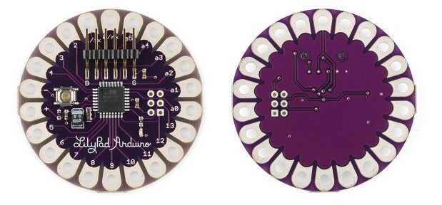
Despite its small size, 5 cm in diameter and 0.8 mm thick, this circular board is supplied with 22 pins (14 I/O digital pins, 6 I/O analog pins, 2 pins for power). These pins are distributed along the perimeter as the petals of a flower, and have a shape such as to allow the electrical contact even by sewing.
The core of this small card is the ATmega328 microcontroller, or the advanced version in which there is the ATMEGA32U4 microcontroller with USB port.
| LilyPad USB ATmega32U4 |
Programming Lilypad does not differ from of all other boards of Arduino. Thus you can use the Arduino IDE without any problem (you can download it from here). To connect the Lilypad to the PC, if you have the board in the USB version (ATMEGA32U4 board) there is no problem, just a USB cable with a micro USB terminal. While if you have available the classic version of the card (ATMega328 board) you need to use an USB-FTDI adapter.
| Sparkfun FTDI Basic Breakout 5V |

You can download the datasheet.
| Microcontroller | ATmega168V or ATmega328V |
| Operating Voltage | 2.7-5.5 V |
| Input Voltage | 2.7-5.5 V |
| Digital I/O Pins | 14 (of which 6 provide PWM output) |
| Analog Input Pins | 6 |
| DC Current per I/O Pin | 40 mA |
| Flash Memory | 16 KB (of which 2 KB used by bootloader) |
| SRAM | 1 KB |
| EEPROM | 512 bytes |
| Clock Speed | 8 MHz |
Sew a circuit
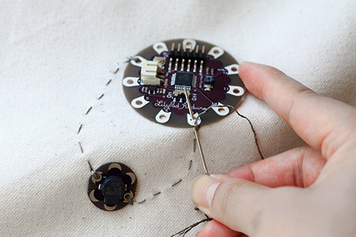
In addition to the Lilypad board, the Sparkfun Electronics offers a whole series of accessories that can be sewn. Since their purpose, Lilypad and all accessory components must meet special requirements: in fact, thet have a high degree of flexibility, but not only … all components, including the Lilypad board can be washed by hand!
Thus buttons, sensors, and LEDs can be sewn on clothes in particular positions, so as to perform specific functions. All these elements are sewn using conductive wires so as to realize a circuit.
| Lilypad button | |
| LilyPad Coin Cell Battery Holder – Switched – 20mm | |
| LilyPad MP3 |
On the Internet there is a nice tutorial that explains in detail how to sew a circuit incorporating the various elements on a dress. The tutorial is available at LilyPadarduino.org, a beautiful site dedicated to all the lovers of this fantastic board.
Electronic Traces – visual sensations with dance steps
In my opinion, one of the best apps that have been created with the LilyPad isElectronic Traces. This project allows you to create digital paintings through the movement of the dancers.
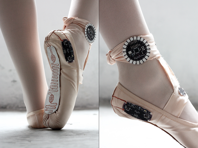
Thanks to a series of motion sensors and pressure sewn on dance shoes, the Lilypad board allows you to capture the movements of the dancer turning them into visual sensations. The signals collected from the Lilypad board are sent to an electronic device, such as a smart phone. An application then converts this data into very appealing graphic displays.
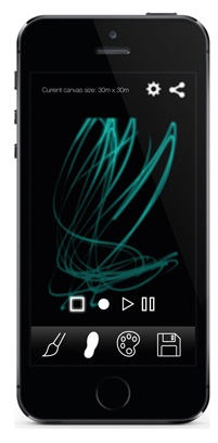
The images created can also be converted into a movie. A possible application could be to a dancer that uses these movies in order to analyze its movements and then fix them.
Here’s a great video:
[vsw id=”108109673″ source=”vimeo” width=”425″ height=”344″ autoplay=”no”]
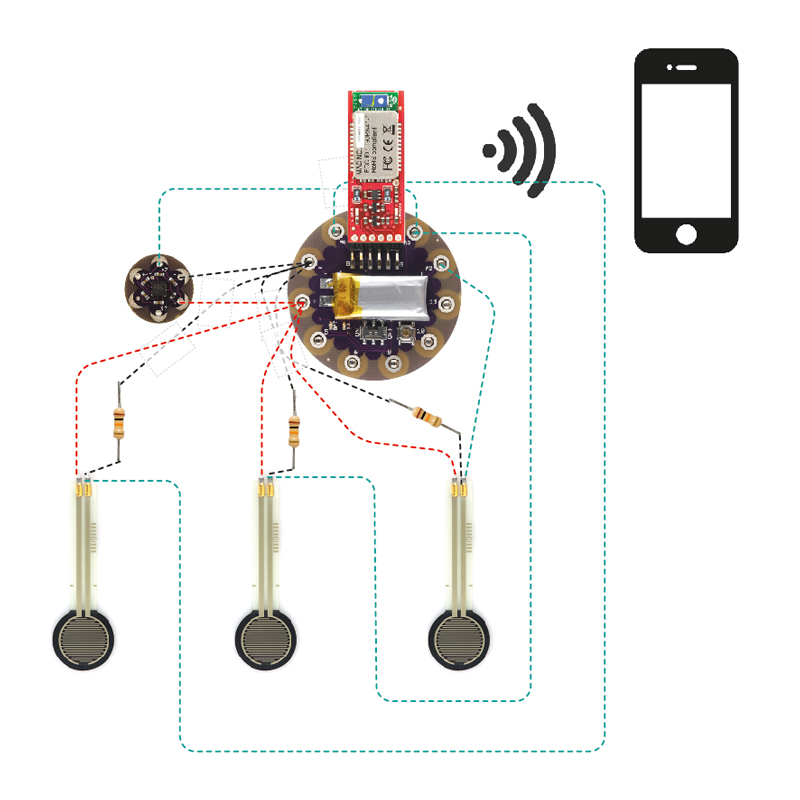
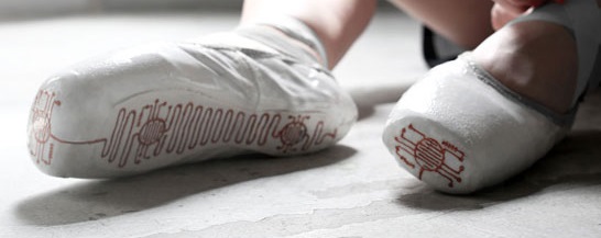
The circuit to be realized, or better to sew on the shoe is really very simple. From the photos available on the website (see Figure 7 and 9), you can see an accelerometer (Figure 10), which will track the movement of the foot. The accelerometer in question is the SparkFun DEV-09 267, or better, a small card which has an integrated three-axis accelerometer ADXL335 MEMS AnalogDevice that provides an analog signal of 0 to 3V for each of the three Cartesian axes X, Y and Z .
| Accelerometro ADXL335 per Lilypad |
In addition to the accelerometer, a series of touch sensors are connected to the Lilypad. These sensors are sewn on the tip of the shoe, heel and sole of the foot. These force sensors will indicate the various levels of pressure at which the shoe is subjected during the movement of the dancer.
Wireless Controlled Robotic Hand
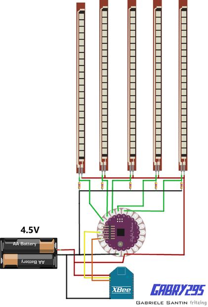
This is the project proposed by an Italian guy Gabriel Santin. It consists of an artificial hand controlled by a glove fitted with flex sensors totally wireless. The LilyPad board is sewn on the back of the glove,
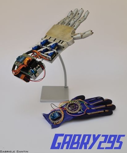
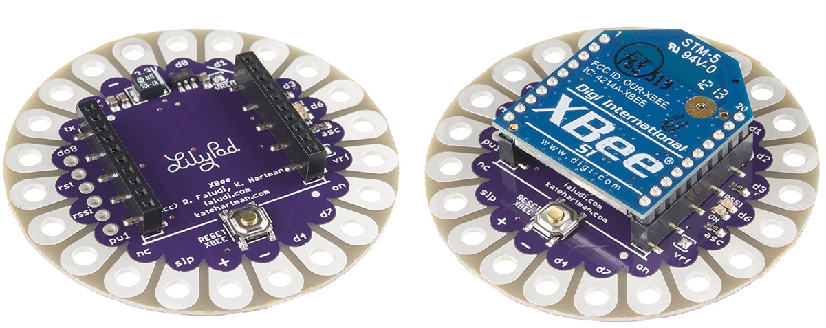
The ability to wirelessly manage the control of artificial hand is due to the addition of an accessory board on which you can mount a Xbee module.
Here is the circuit diagram that describes the circuit sewn on the glove
In Internet there is a very nice post in which Gabriele Santin (the project maker) describes how to build this project. Moreover, there is also a video:
On the Internet there is a wonderful article written by Gabriel Santin which describes how to make this wonderful project, see here. Also, here is a video of the project:
[vsw id=”efO-ooyS-mo” source=”youtube” width=”425″ height=”344″ autoplay=”no”]
Conclusion
I hope this article and the two projects presented in this article will have stimulated the desire to create your own design and wear it! See you at the next article. Bye