Introduction
With the availability of an Arduino board, most likely after learning how to create your first circuits, you will certainly want to utilize your board to control a motor. Among the wide selection of motors that you can use:
- DC motors
- Stepper motors
- Servo motors
There are many specific tutorials according to the type of motor and of their voltage.
But how can I practice with all these motors, using less material as possible and keeping myself in a situation that is as general as possible?
Adafruit has recently made the second version of a board shield for Arduino: the Adafruit Motorshield v2 board.
This board allows you to drive and control all three types of motors (only low-power motors). And with only one board you can control at the same time:
- 4 DC motors
- 2 stepper motors
- 2 servo motors
But actually, this board is a stackable shield that uses the I2C protocol to cominicate with Arduino. Thus, it is possible to use several boards of the same type, mounting them, one above the other, each set with its own I2C address. Therefore with this stack configuration it is possibile to control a unlimited number of motors from a single Arduino board.
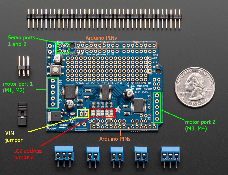
The Adafruit Motorshield v2 board
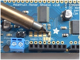
The core of this shield is the motor driver chip Toshiba TB6612FNG (here you can find all the technical specifications). In the following figure you can see it in the middle of the board.

Per programmare questa scheda mediante l’IDE di Arduino è disponibile una libreria specifica per questa versione.
The Adafruit Motorshield v2 library
To use the shield on an Arduino, you’ll need to install the Adafruit Motorshield v2 library. You can download it from:
Note: be careful, because available on line there is the AF_Motor library which is used for v1 shields and it is not compatible with the new Motorshield v2.
You can recognize the right library because it is so structured:
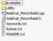
From the github site you can download the Zip file containing the library. Extract the content and copy it within the directory:
C://users/myname/My Documents/Arduino/libraries
Now if you run the Arduino IDE, you will find the Adafruit Motorshield examples loaded into it.

As you can see from the list, the library comes with a set of examples.
DC Motors
You can start working with DC Motors. The Adafruit MotorShield can control up to 4 DC motors, powered by 5-12V.
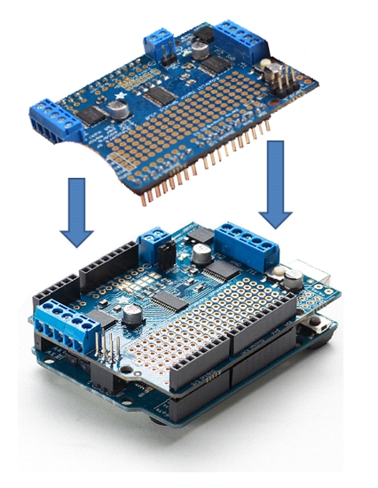
Plug the shield into the Arduino and connect a DC motor to motor port 1 (M1). It does not matter which wire goes into which terminal block as motors are bi-directions. Connect to the top two terminal ports; do not connect to the middle pin (GND). See the photo below for the red and blue wire example. Be sure to screw down the terminal blocks to make a good connection.

There are two ways to apply power to the motor:
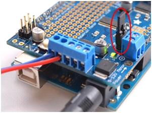
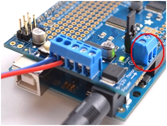
1) You can power the Motorshield and the DC motor via the DC Barrel Jack or USB port and insert the VIN Jumper shown as the tall black handle right next to the green Power LED below.
If the Green LED isn’t lit up brightless, do not continue. The power supplied by the Arduino board is not enough, so you need to connect the motorshield as shown in the following way.
2) You can power the Motorshield and the DC motor via the 5-12V-DC motor power terminal port, the double terminal block next to the green Power LED. Don’t forget to remove the VIN jumper.
In the IDE, load and run the following example: File->Example->Adafruit_MotorShield->DCMotorTest
You should see and hear the DC motor turn on and move back and forth, each time first accelerating and then decelerating. If you attach a slip of tape as a flag, you can see the movement just described.
Now let’s analyze the code of the example.
First, it is necessary to include the libraries:
#include
#include
#include "utility/Adafruit_PWMServoDriver.h"
The Wire library
This library allows you to communicate with I2C/TWI devices. On the Arduino board, there are two pins dedicated to the I2C protocol: A4 for the SDA (data line) and A5 for the SCL (clock line).

The first thing to do is to create the Motorshield object:
Adafruit_MotorShield AFMS = Adafruit_MotorShield();
The Adafruit_MotorShield class represents a single motorshield and it must be declare at the beginning before using any object of the library. If you have multiple stacked motorshields, it will be necessary to declare a motorshield object for each shield.
The constructor
Adafruit_MotorShield(uint8_t addr = 0x60);
takes as optional parameter the I2C address of the shield. The default address is 0x060 which is the address assigned by default to any Adafruit motorshield. If you need to use several motorshields you need to assign a unique and different I2C address for each shield.
Adafruit_DCMotor *myMotor = AFMS.getMotor(1);
The function
Adafruit_DCMotor *getMotor(uint8_t n);
returns one among 4 DC motors to be controlled by the shield. The n parameter specifies the associated motor: 1-4.
void setup(){
   AFMS.begin();
}
The function
void begin(uint16_t freq = 1600);
must be declared within the setup() function. It initializes the shield for using the DC motor. It takes the freq parameters, which is the PWM frequency. By default, the frequency used is 1.6KHz.
void setup(){
   ...
   myMotor->setSpeed(150);
   myMotor->run(FORWARD);
   myMotor->run(RELEASE);
}
The function
void setSpeed(uint8_t speed);
controls the power level with which the shield provides the motor. The speed parameter is a value between 0-255.
Note: the setSpeed functions only controls the power provided to the DC motore. The actual speed of the motor depends on several factors, including:
- Type of motor
- Power supply
- Load
The function
void run(uint8_t direction);
sets the direction in which the motor rotates. The direction parameters can only assumes three values:
- FORWARD (rotating forward)
- REVERSE (rotating backward)
- RELEASE (stop rotation)
Note that the “forward” and “backward” directions are arbitrary. If they do not correspond with the desired direction, you have to invert the wires to the M1 port.
This snippet moves forward the motor with an acceleration from standstill to the maximum speed (255):
void loop(){
   ...
   uint8_t i;
   myMotor->run(FORWARD);
   for(i=0; i<255; i++){ myMotor->setSpeed(i);
      delay(10);
   }
}
Instead in order to decelerate the motor rotation you have to write:
void loop(){
   ...
   for(i=255; i!=0; i--){
      myMotor->setSpeed(i);
      delay(10);
   }
}
Servo Motors
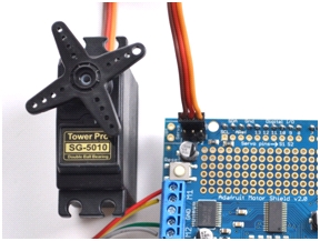
Hobby servos are a good example for get familiar with motion control (a sub-field of automation). This type of motor has a 3-pin wire (+5V,ground, signal). The Adafruit motorshield in this case acts only as an intermediary, transmitting the 16bit signal PWM from Arduino to the Servo motor. Thus, when you deal with servos you do not need to use the Adafruit Motorshield library, but include directly the Servos library.
#include
To connect the Servo in the right way, respecting the color of wires as shown in figure. On the shield you can control up to two Servo motors. If you need to control more than two you need to find another solution (I will show a good solution in a next article as soon as possible) instead to use stacked motorshields.
In the library there is no example code for controlling only servos. Anyway here’s an example that may well elucidate the same functionality you have seen before with DC motors and you also see later with stepper motors.

Now, let’s analyze the code as reported here:
Servo myServo;
int angle = 0;
void setup(){
   myServo.attach(9);
}
You must declare each servo motor you want to use, using the Servo class. With the attach() function you can assign to each motor the pin out to use as parameter.
attach(10) -> you are assigning the Servo1 pin out on the board to the motor;
attach(9) -> you are assigning the Servo2 pin out on the board to the motor;
With the following code, you rotate the servo motor in both directions covering all the angle range [0-180°] and viceversa.
void loop(){
   for(angle=0; angle < 180; angle += 1) { myServo.write(angle); delay(20); } for(angle=180; angle >= 1; angle -= 1){
      myServo.write(angle);
      delay(20);
   }
}
STEPPER MOTORS
The Adafruit Motorshield can run unipolar (5-wire and 6-wire) and bipolar (4-wire) steppers. It cannot run steppers with any other number of wires! The code is the same for unipolar or bipolar motors, the wiring is just slightly different.
In this case, differently from the DC motors, the wire order does matter, so first, it is necessary you know the function of every wire. You can connect two stepper motors to the motorshield board, which provides 2 motor ports of 5 pins.

The coil#1 of the motor must be connected to the top two terminal pins (M1 or M3) and the the coil#2 to the bottom two terminal pins (M2 or M4). Thus, depending on the stepper motor you have to make different connections.
- If you have a bipolar motor, that is 4-wire motor, connect the two coils as indicated above, leaving the GND pin not connected.
- If you are using a 5-wire unipolar motor, connects the common wire to the GND.
- If you are using a 6-wire unipolar motor, you can connect the two center coil wires together to GND.
You should provide a further 5-12V DC power to the shield if you want to be sure to get a good performance (for 1 motor without load, the power provided from Arduino is enough). Check if the power LED lit up brightly.
Once you have done the connection you are ready to use the code.
There is an example provided from the library to use this type of motors.
In the IDE, load and run the following example: File->Example->Adafruit_MotorShield->StepperTest
If you run the code, the stepper motor moves forward and backward in a similar manner of what we have seen with the DC motors.
Let’s analyze the code. First you need to include the libraries.
#include
#include
#include "utility/Adafruit_PWMServoDriver.h"
Then, you need to declare an Adafruit_MotorShield object:
Adafruit_MotorShield AFMS = Adafruit_MotorShield();
Now you have to declare a motor object for each motor.
Adafruit_StepperMotor *myMotor = AFMS.getStepper(200,2);
The
Adafruit_StepperMotor *getStepper(uint16_t steps, uint8_t n);
function returns one of the 2 stepper motor object as defined with the n parameter. The steps parameter specifies the number of steps per revolution. You need to calculate this value depending on the motor you are using. For example, a 7.5 degrees/step motor has 360/7.5 = 48 steps. Instead, regarding the n parameter, if you connect the motor to the M1 and M2 ports then you must specify 1, else if you connect the motor to the M3 and M4 ports then you must specify 2.
Once you have defined the motor objects, you can define the setup() function.
void setup(){
   AFMS.begin();
   myMotor->setSpeed(10);
}
Differently from DC motors, the parameter passed to the setSpeed() function is the actual speed in rpm.
In the loop() function we will add all the movements. Every time you want the motor to move, you will call the
void step(uint16_t steps, uint8_t dir, uint8_t style = SINGLE);
function. The steps parameter specifies how many steps to move, the dir parameter specify the direction (FORWARD or BACKWARD) and the style parameter specifies the stepping style (SINGLE, DOUBLE, INTERLEAVED or MICROSTEP).
The step() function is synchronous and does not return until all steps are complete. When complete the motor remains powered to apply “holding torque” to maintain position.
void loop(){
myMotor->step(100, FORWARD, SINGLE);
myMotor->step(100, BACKWARD, SINGLE);
}
Let’s see in details the four different styles of rotation.
- SINGLE means a single-coil activation
- DOUBLE means the 2 coils are activated at once (for higher torque)
- INTERLEAVE means that it alternates between single and double to get twice the resolution (but of course its half the speed)
- MICROSTEP is a method where the coils are subjected to a PWM to create smooth motion between steps.
By default, the motor will hold the position after every stepping is done. For releasing all the coils, you need to call the
void release();
function. This function removes all power from the motor. If you do not need to hold the torque during some operation, it is best practice to call this function in order to reduce the power requirements.
Addressing the shield
If you wish to stack the shields it is necessary that each one must have a unique I2C address. If you leave unchanged the board, the default address is 0x60. But you can easily assign an I2C address to the shield within the range [0x60-0x80] for a total of 32 unique addresses.
You can assign them using the address jumpers on the lower edge of the board. To set the I2C address, you use have to use a drop of solder to bridge the corresponding address jumper for each binary ‘1’ in the address. The right-most jumper is the address bit #0, then to the left of that is address bit #1, and so on up to address bit #5.
[:]