
Introduction
This is the second part of the article published about a week ago that concerned the PIR motion sensors, explaining the technical details on their usage and operation (see here). In this article, continuing with the topic, you will see how to use them in a more practical way, or better, by using an Arduino board (in my case an Arduino UNO).
Connetting PIR with Arduino
You will then begin, precisely from the point at which the previous article had been interrupted, that is, with the connection diagram realized with the Fritzing software. I changed the color of the central cable coming out from the PIR representing it with the white color, so that it will be consistent with my RIP model.
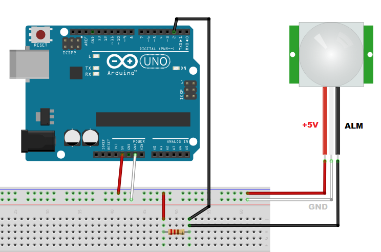
In the previous article you had seen that the color, the functionality and the arrangement of the three output cables may vary depending on the PIR model. So, before making any connections, it is important that controls the datasheet of the model in possession.
In the sketch above, I drew the connections basing on my PIR model, the SE-10. If your model should be different, and especially in the disposition of the cables, change the connections accordingly. The red wire is the +5V power supply, the white wire is the GROUND, and the black wire is the ALM which is the detection signal coming from the sensor. Moreover, you can notice a resistance in the sketcg, this must be 1kΩ.
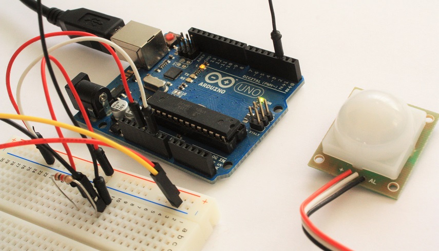
Here is a picture showing the actual circuit…
First example: counting the detected movements
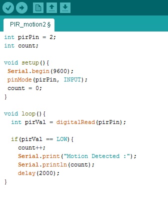
As a first example, write a program that will count as many times that the PIR has detected motion. First, set the PIN 2 as input with the pinMode() function. The program practically consists in reading out the value from the PIN 2 overtime.
Generally, in absence of detection the state of this pin will be HIGH. When the PIR sensor detects motion, it will bring the status of the pin to LOW level. When this happens, the condition if() inside the loop is activated and then you can create a response event. In this case a simple message will be sent via serial containing the words “Motion Detected” and the number of the movement detected.
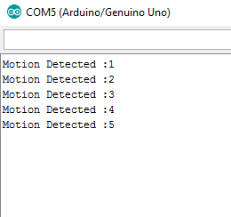
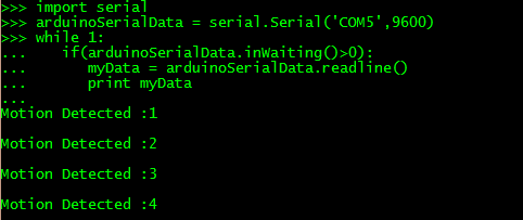
After editing the code, please complete and submit it to the Arduino board. If there are no errors, Arduino will begin to execute code as soon as you open a serial connection. In order to open a serial communication with Arduino IDE go to Tools > Serial Monitor. You will see a new window, in which the words “Motion Detected” with the count number will appear every time a every time the PIR detects a motion
Or if you prefer to use Python from the command line, open a terminal session (cmd in Windows) and run the command:
$ python
and then insert the following commands:
>>>import serial
>>>arduinoSerialData = serial.Serial('/dev/ttyACM0',9600)
>>>while 1:
     if(arduinoSerialData.inWaiting()>0):
        myData = arduinoSerialData.readline()
        print myData
You will get the serial output sent from Arduino.
If you write the import serial command, you receive an error message, then the pySerial library (required for serial communication via Python) has not yet been installed. You can do it with pip or Anaconda (depending on which system you are using).
$ pip install pyserial
or
$ conda install pyserial
The HIGH and LOW status of the INPUT PIN with the Pull Up resistor.
When the sensor is powered, as already described in the previous article, the RIP module will take 1-2 seconds to calibrate itself. Once the calibration is done, the PIN alarm (open-collector) will show the LOW level only when motion is detected (the status of the pin alarm is not latched). Normally, that is when no motion is detected, the alarm PIN is in a state of floating.
This setting of the open-collector allows you to connect multiple PIRs on the same input PIN on the Arduino board, but it also means that you will need to use an external pull-up on pin ALARM. When any of the sensors will sense a movement, the state of the PIN will assume to the LOW status.

Second example: how to display the PIN status
Now you modify the previous example in order to observe the voltage state from a computer. In fact, you will use Arduino itself, as a kind of voltmeter to directly observe what happens to the ALARM signal when the PIR is at rest and when it detects motion.
To do this, you will use the two analog PIN A0 and A1 mounted on the Arduino board, and by connecting two dupont jumper cables, you will use them as probes for follow the trend of the voltage at two different points of the circuit.
The Fritzing sketch shown below, shows the previous sketch with some changes. All the existing connections are drawn in black, while the two new connections are drawn with the colors green (Ch1) and red (Ch2). Then you will analyze the signal at both ends of the pull-up resistor.
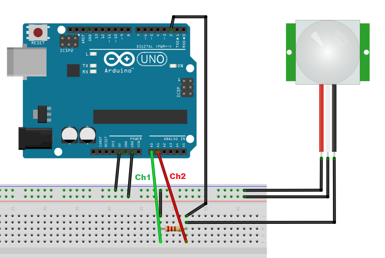
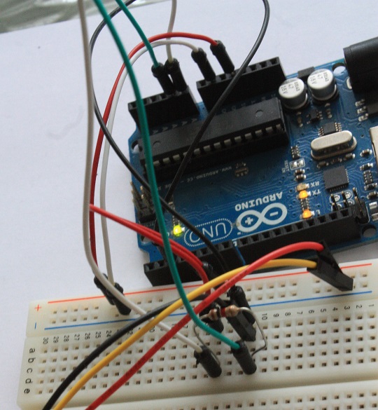
This is the actual circuit…
Now you can change the code on the Arduino IDE, adding the code for the control of two channels, and removing the management of the event in motion detection, which in this example are not interested in managing.
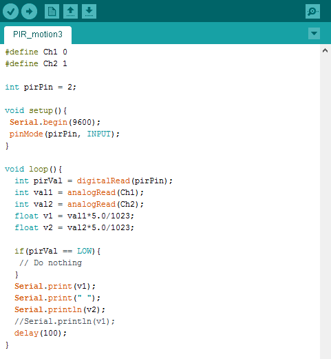
First, you defined two new analog channels Ch1 and Ch2 on analog pins A0 and A1 on Arduino. You will use them as probes to be inserted into specific points of the circuit. The readings are taken through the analogRead() function. Readings shall be converted to voltage, and since the maximum value is 1023 and it is equivalent to 5V, you can make the appropriate changes to the val1 and val2 readings. The floating point values v1 and v2 will be sent serially in a same row.
This data is received from a program written in Python and displayed in real time. Online, I found a python program suitable for the purpose written by Mahesh Venkitachalam (see here). I modified slightly the code in order to adapt it to receive values in Volts (float values).
import sys, serial, argparse
import numpy as np
from time import sleep
from collections import deque

import matplotlib.pyplot as plt
import matplotlib.animation as animation

# plot class
class AnalogPlot:
   # constr
   def __init__(self, strPort, maxLen):
      # open serial port
      self.ser = serial.Serial(strPort, 9600)
      self.ax = deque([0.0]*maxLen)
      self.ay = deque([0.0]*maxLen)
      self.maxLen = maxLen

   # add to buffer
   def addToBuf(self, buf, val):
      if len(buf) < self.maxLen:
         buf.append(val)
      else:
         buf.pop()
         buf.appendleft(val)

   # add data
   def add(self, data):
      assert(len(data) == 2)
      self.addToBuf(self.ax, data[0])
      self.addToBuf(self.ay, data[1])

   # update plot
   def update(self, frameNum, a0, a1):
      try:
         line = self.ser.readline()
         data = [float(val) for val in line.split()]
         # print data
         if(len(data) == 2):
            self.add(data)
            a0.set_data(range(self.maxLen), self.ax)
            a1.set_data(range(self.maxLen), self.ay)
      except KeyboardInterrupt:
         print('exiting')
      return a0,
   # clean up
   def close(self):
      # close serial
      self.ser.flush()
      self.ser.close()

# main() function
def main():
   # create parser
   parser = argparse.ArgumentParser(description="LDR serial")
   # add expected arguments
   parser.add_argument('--port', dest='port', required=True)
   # parse args
   args = parser.parse_args()

   strPort = args.port
   print('reading from serial port %s...' % strPort)
   # plot parameters
   analogPlot = AnalogPlot(strPort, 100)
   print('plotting data...')
   # set up animation
   fig = plt.figure()
   ax = plt.axes(xlim=(0, 100), ylim=(0, 6))
   ax.set_ylabel('Voltage V')
   a0, = ax.plot([], [])
   a1, = ax.plot([], [])
   anim = animation.FuncAnimation(fig, analogPlot.update,
                                  fargs=(a0, a1),
                                  interval=50)
   # show plot
   plt.show()

   # clean up
   analogPlot.close()
   print('exiting.')

# call main
if __name__ == '__main__':
   main()
Once you have finished to edit, save it as voltage_reader.py. The program can be lanched from the command line, passing as an argument the listening port. In my case, on Windows, the listening port is COM5.
python voltage_reader.py --port COM5
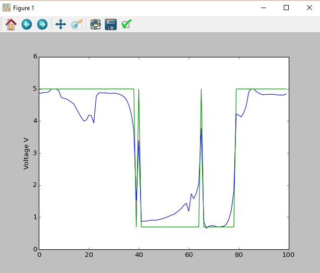
and suddenly a window will appear showing the two voltages sent by Arduino. This window will show their trends overtime.
As you can see, the green line corresponding to the power supply, remains stable at 5.00V, while the blue section, corresponding to the Alarm PIN, switches to LOW (0.70V) whenever motion is detected by the PIR sensor. The duration of the LOW state will depend on the duration of the movement. As soon ceased the movement as the state will return to HIGH (5.00V).
Now, just for curiosity, you can move one of the two probes, and more precisely the one that remains stable at 5.00V (the supply at 5.0V). Move it in order to point it directly on one of the three sensor terminals (and not the module’s three). Let’s see what happens.
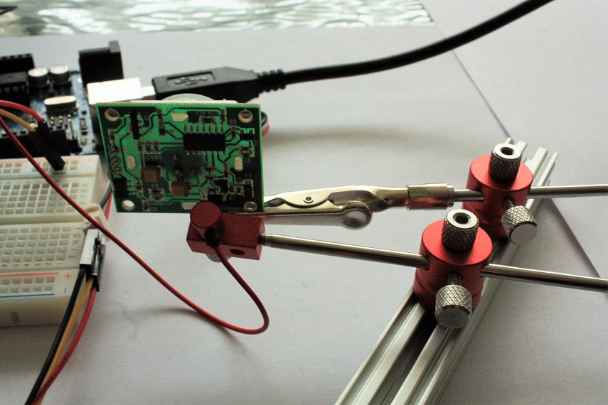
For doing this, I used the PCBGrip kit for building the probes (if you are interested to the topic, I recommend you to read this article ).
Now, you can launch again the python program in order to see the trends.
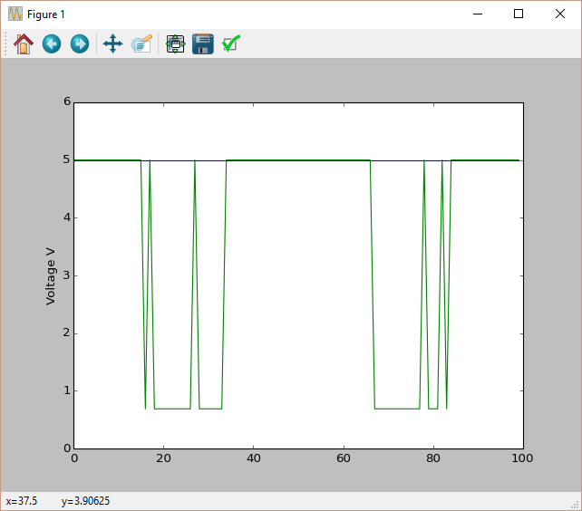
You can notice that the blue line is the actual ALARM signal not filtered from the electronic circuits printed on the PIR module board. 🙂
Conclusions
The topic certainly does not end here. But the purpose of this article was to illustrate how to use the PIR sensor with Arduino, but also to show new approaches to study better the behavior of these sensors.
Do you have experience with Arduino to share? We’re looking for people interested in publishing new articles. We don’t look for experts, but for Arduino’s enthusiasts. Let us know. Do not be afraid (for any problem we can help you). For more information, contact us directly sending an email to meccanismo.complesso@gmail.com, or at least leave a comment!