Introduction
The prototypes (from the greek πρωτότυπος ‘Prototipos’ ie ‘first model’) are often intended as partial or approximate models of a system that we want to develop (design phase) and their realization is often a very critical stage in the production process. But we can consider even physical models made in a single copy (or at least in a small number) as prototypes for purposes other than production, often for purposes of study or analysis.
For the realization of a prototype, the classical methodology is in keeping with the classical conception of industrial mechanical production: the processing of the starting material by chip removal (subtractive method). Also the production by forming (applying thermal or mechanical forces to starting material to produce the object by deformation) makes use of molds which in turn are generated for subtractive methodologies.
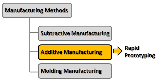
In recent years, in reality it is becoming increasingly popular the completely opposite approach: namely the creation of a prototype using the gradual deposition of material (additive methods) in order to obtain the physical model in its entirety. In general, we refer to this concept and the technologies that make it possible as rapid prototyping.
The Rapid Prototyping
Thus, the rapid prototyping (RP) is the set of all the technologies that make possible the production of a prototype in a few hours and with ease, while also reducing the costs of realization.
Often rapid prototyping is also used for the realization of the master to be used in the creation of molds for the production of objects in series.
Usually you start with a 3D model created with a three-dimensional CAD (Computer Aided Design). Passing through various stages and subjecting the model to different procedures, you “translate” it into a physical model and a real prototype.
For the “translation” from a mathematical model to the physical model, we then provide a whole range of new innovative technologies that are always based on the principle of additive methods of production.
- Stereolithografy (SLA)
- Selective Laser Sintering (SLS)
- Fused Deposition Modeling (FDM)
- Laminated Object Manufacturing (LOM)
- InkJet Printing Techinques
However, whatever the technique implemented, the rapid prototyping process passes through various stages common to all techniques.
- Designing with 3D CAD
- Generating STL files
- Orientation and supports generation
- Slicing
- Realization (3D printing)
- Supports removal, cleaning, finishing
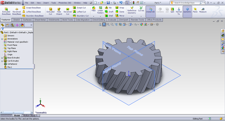
Designing with 3D CAD
For the creation of three-dimensional models that will then form the desired object, you can make use of three-dimensional CAD systems. These systems are nothing more than highly specialized software in the design, planning and implementation of mathematical models.
Generally the files that are generated by a large number of CAD available (both commercial and free) have as many output formats. However, for rapid prototyping, the format to which you can refer, is the STL (Standard Triangulation Language) that has become the standard for this kind of models.
The three-dimensional model is converted to a Mesh model in which the outer surface is approximated by triangles of different sizes depending on the required resolution. The higher the resolution, the smaller will be the size of the triangles, the better the model profile, the greater will be the resources and time that will require the calculation model.
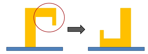
Orientation and supports generation
As you will see in the following section, all rapid prototyping techniques are based on printing a solid object by adding the material layer after layer. Thus, the object must be produced from the base up to the top whereas as a printing layer each its section. One of the fundamental problems is that each section to be produced must be properly supported by the layer deposited previously. Therefore if the model has protruding parts, it will be practically impossible to apply the upper layers without the aid of supports. Moreover, the amount of media required and the quality of printing depends heavily on the choice of the orientation in which we want to print the object. Indeed, given that the printing goes from the bottom to the other, depending on the model shape more or less irregular, the choice of a particular orientation can greatly facilitate the printing process and decrease the number of necessary supports.
The generation of supports however, is an operation that is carried out by specialized software in this kind of operations; often they are plugins to be integrated into the CAD software. The supports generated in this way will ultimately be additional parts to our model that will be printer together with it. In the process of finishing these supports must be removed.
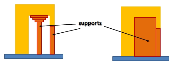
With some techniques support can be made from a different material than that of the prototype and this is done precisely to facilitate its removal later. Furthermore depending on the technique or the nature of the material used, such support may be either totally fillers volumes not occupied by our model or be minimized (in the form of columns).
Slicing
All rapid prototyping techniques are based on the concept of deposition of layers of material to form the solid in its entirety. So whatever is the three-dimensional model we want to produce it will be necessary to break it down into sheets of material (slices), each of which will have a different shape. This process is called slicing.
Even this process as the previous ones is performed by specific software which are able to generate and optimize all the layers of which the three-dimensional model will be composed. As the other steps of the rapid prototyping, there are several methods and algorithms to accomplish the slicing.
In fact, depending on the thickness of the layers, the effect of the step-like curved surfaces will be more or less evident. The smaller the thickness of each layer, the better the printing of curved surfaces. But increasing the resolution also the time and resources required will be increased. In addition, the thickness of the layers is a factor delimited by rapid prototyping technique with which we decide to perform printing. If the technique, or rather the tool with which to carry out such a print, is able to produce layers of different thicknesses, then a good methodology to be applied to the process is the adaptive slicing.
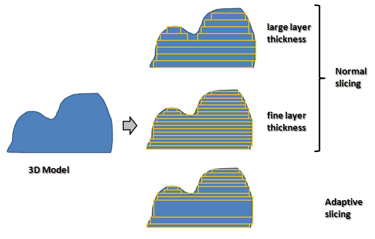
Indeed, if we establish a specific thickness for each layer, during slicing we note that some adjacent layers will have the same shape. In this case, why bother to lay more equal layers one above the other if you can lay one? In addition, the smaller the thickness of the layers chosen the greater the probability of finding the overlying layers with the common form. In this case the technique of adaptive slicing is really the most effective.
Manufacturing Tecniques for rapid prototyping
Once you create the three-dimensional model of the prototype with the CAD technology, generated supports and performed the slicing process, you can go to the physical implementation of your model, or rather the printing of a prototype. Nowadays there are many available rapid prototyping techniques with which to build your prototypes, each with different characteristics. The choice of a technique is very often due both to the purpose of the prototype and to economic resources that you have.
Let’s see the rapid prototyping techniques that are most commonly spread and which are available on the market.
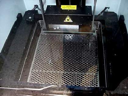
Stereolithography (SLA)
This method is considered as the first rapid prototyping process that has been developed (3D Systems, USA, 1986).
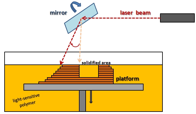
A platform that can move vertically is enclosed in a tub that is subsequently filled with a photosensitive resin. The starting point of the platform is just the surface level of the resin. The platform then is gradually going down with steps of approximately 0.1mm which will constitute the layers (layers) of which will be composed of the object to be produced.
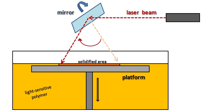
Indeed, the resin surface is struck by a laser beam and the points struck solidify, thus leading, layer after layer, the formation of the solid object.
When the last layer is completed, the object is removed from the tub and cleaned the liquid resin.
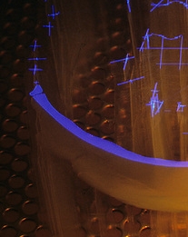
The laser hits the surface of the resin layer after the other
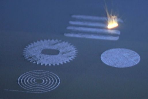
Selective Laser Sintering (SLS)
This methodology was developed in 1989 (from DTM, USA). Compared to stereolithography, it solves many problems concerning the nature of the material used to make the prototype. With this technique it is possible to use a large number of materials, materials that can reproduce the properties of thermoplastics such as polycarbonate and nylon.
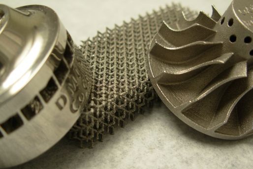
It is important to add at this point the technique Direct Metal Laser Sintering (DMLS) that among all the techniques of rapid prototyping is the most recent (EOS, Germany, March 2012). is pretty much the Laser Sintering with the direct production of metal components.
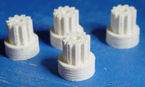
Fused Deposition Modeling (FDM)
This technique is based on a different principle than the techniques seen so far. This technique has been realized for the first time at the end of the 80s, but only used commercially since the 90’s. Perhaps today it is the technique most commonly known and one to which we refer when we speak of 3D printers. It makes use of a purely standard plastic materials (ABS, PC) in the form of filaments wound into coils.
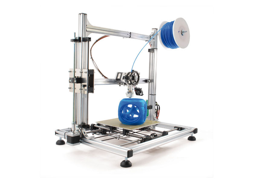
The plastic filament is passed through a augello (extruder) which heats making it semi-molten. The material made so malleable is deposited in layers on a mobile platform, and cooling almost instantly it binds with the material underneath and side. Layer after layer (which may vary depending on the model, however tenths of a mm) so it will go to form the solid object.

The advantages of this technique are clearly visible in the spread almost homely of 3D printers. The cleanliness of the process (leaves no slag, dust, or liquids) along with the relative low cost, ease of use and the smaller size of the instrumentation for printing with this technique, were the key factors for its rapid success. The only thing still to be improved is that the products obtained with this technique are still inferior to those obtained with other techniques is rapid prototyping.
However, the rapid development and diffusion of this technique will certainly lead to gradual improvements to achieve, if not exceed, the levels achieved by other techniques.
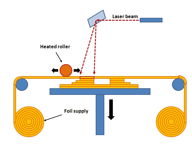
Laminated Object Manufacturing (LOM)
Developed by Helisys Inc. this technique consists in the gradual overlapping adhesive foils of paper, plastic or metal. These sheets are cut and glued together specially, thus forming, layer after layer the physical object.
The material produced by this technique looks very similar to wood.
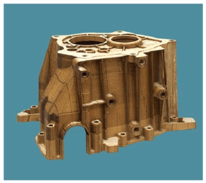
Although the accuracy of this technique is inferior to the other, it has to its advantage the low cost of the material used and the possibility of building large objects.
Solid Ground Curing (SGC)
Developed for the first time by Cubital Ltd. (1986), this technique relies on the generation of the various layers by exploiting their exposure to a UV lamp high power through the use of appropriate masks. The material (liquid photopolymer) solidifies when exposed to UV light and thus the exposure of certain partial points leads to stratification solid of this polymer to form the desired object.
This technique is very complex and expensive, and so it was abandoned.
Conclusions
I must conclude that this topic fascinates us all a little bit, especially lately, which is always stronger than the intension to buy a 3D printer at little cost and put yourself out there to realize our prototypes.
With this article I wanted to give a quick overview of the current context of rapid prototyping in order to give everyone an idea of what it is. But above all, as you can see, today it is always easier and more accessible to perform a “homemade” prototyping.
I hope that this article has piqued your curiosity further and who knows … if you are experienced and / or have had experience in this area, I invite you all to add your knowledge to this article.[:]