
Introduction
One of the fundamental principles of electronics is modularity. This has always been one of its winning aspects since all the projects can be subdivided into modules, which in turn are subdivided into additional modules and so on. This has made all the projects easily executable and manageable, where each module can be considered separately, improved and replaced. However, this efficiency has made another aspect indispensable: communication between the various modules. This article will start with a general overview to further deepen and analyze the serial communication in detail.
Parallel and serial communication
Parallel communication is based on interfaces that are able to transfer multiple bits at the same time, using a data bus. These data buses are generally transferred through a set of 8, 16, 32, … wires on which the signals only assume binary values like 0 and 1. This is a bus, 8, 16, 32 bit. In addition to these cables there is an additional one called CLK (clock) whose purpose is to scan the moment when the bits must be read (bytes).
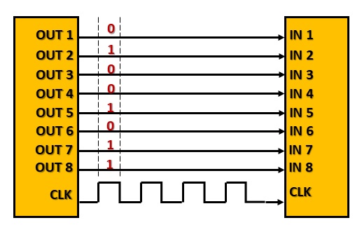
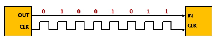
On the other hand, serial communication is based on a stream of bit transferred over a single cable, in which the bits are transferred one at a time. Again in this case there is a second communication channel called CLK (clock) that marks the reading time of each single bit. So the serial communication is based only and always on 2 single cables.
Parallel communication is therefore more efficient: it is faster, simple, and relatively easy to implement. But there is one aspect that needs to be taken into account: it requires many I / O lines. This in some cases is really a problem since many microprocessors do not have many I / O ports available and a parallel communication would take many, too many. So often it is used for serial communication, though it is less fast, however, it can still use a few channels.
Asynchronous serial communication
Over the years, many types of serial protocols have evolved over time to meet largely the needs of the moment. Some of these, such as USB (Universal Serial Bus) and Ethernet, have been very successful and are known to the profane. Other protocols such as SPI and I2C are known and used by the electronics industry. But there are many other protocols, each one specializing in a particular purpose.
Generally, all serial protocols can be divided into two groups: synchronous and asynchronous.
A synchronous serial communication is always coupled with a CLOCK signal, so that all devices on the serial bus share a common clock. This particular configuration allows a simpler and often faster data transfer, but also requires an additional channel to communicate. I2C and SPI are two synchronous serial communication protocols.
An asynchronous serial communication, on the other hand, does not use an external CLOCK signal and therefore requires less I / O channels for communication. At the expense of this, a reliable system for transmitting and receiving data must be implemented. The most common serial protocols are Bluetooth, Xbee, GPS module.
The rules of asynchronous serial communication
The asynchronous serial protocol is based on an intrinsic mechanism based on some rules. These rules allow you to make data transfer more reliable:
- bits of data
- synchronization bits
- bit of parity
- baud rate
So when two devices set up asynchronous serial communication, it is important that they are configured in the same way, following the same rules.
Baud Rate
The baud rate is a rule (or configuration) that specifies how fast the data is sent on the serial line. It is generally expressed in bps (bits per second) and its inverse value will indicate how much time a single bits occupy in data transmission. This rule allows you to avoid using the CLOCK as you know the length and speed of each individual data bit a priori.
The most common baud rate used is 9600 bps, but there are also many other standard values (2400, 4800, 19200, 57600, etc.). As you can see, baud rate values can also grow, but why not use higher values? Well, in fact these values are optimized depending on the performance of the microcontrollers involved in the communication. You will soon discover that ever higher values will result in more frequent communication errors due to the microcontroller’s workability limit.
Data Framing
In addition to the baud rate rule, there are other rules that work on the sequence of data to be transmitted. It is easy to guess that the data will have to comply with a certain sequence and this particular activity is called framing. In fact, data (which is nothing more than bit packets) is divided into smaller blocks called blocks (or chunks). Each block of data to be transmitted on an asynchronous serial communication must be embedded in a bit frame, which has a particular structure.
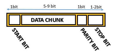
Bits of data
The data to be transmitted is then divided into blocks and embedded in serial packets where other particular bit sequences are also added. The amount of bits inserted in each single packet may vary, typically between 5 and 9 bits, i.e. the length of a byte. So, first, the two communicating devices must be configured to accept and interpret the same amount of bits as a data chunck. But that is not enough, they will also have to match the most significant MSB bit (most significant bit). That is, they will have to agree whether this will be the first or the last bit transmitted.
Synchronization bits
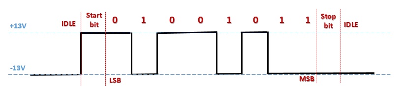
The synchronization bits are 2-3 bits that are added and transferred to each piece of data. These bits are divided into start bit and stop bits. These bits are very important because they define the beginning and end of each data packet. The start bit is always indicated when idle data line switches from state 1 to state 0, while stop bits reset state idle reporting line to state 1.
Parity bit
Parity is a very simple method to check if errors have occurred during transmission. It has only two possible states: even or odd. The parity bit is calculated by summing all the bits of the data chunk, and if the sum is even then the bit is set to 1 (true) otherwise it is set to 0 (odd).
The rule of parity bits, despite their utility, is not always used, as they take time to be analyzed, slowing down the transmission speed.
Serial Bus
A Serial Bus consists of two cables that connect two devices to each other. Each device has two one dedicated data transmission (TX) ports one to receive data (RX). Each cable must be connected to an end with an RX port and the other TX. So each cable will be devoted to transmitting data from one device to another, but not vice versa. The data for each cable will go in one direction.
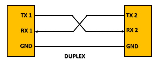
It will also be necessary for both devices to have the same ground level (GND) so that the transmitted data have consistent voltage levels between the two systems. In the graph this is reported as an additional cable that connects the two GND ports of the two devices.
A serial communication in which both devices can send and receive data simultaneously is called full-duplex. While half-duplex is indicated, when the devices are sending the data alternatively, that is, each device will send data in its communication range. Finally there are serial communications where there is only one cable between two different devices, this type of communication is called simplex.
Practical implementation – TTL and RS-232
So far, you have seen serial communication from a conceptual point of view. Now you will see how this can be realized in reality. There are several serial protocols and each one is implemented in a different way. In particular we will analyze two of them among the most common: TTL logic-level and RS-232.
Microcontrollers and other integrated circuits normally communicate by serial means and use it using the TTL (transistor-transistor logic) system. The voltages on the channel can be two: Vcc and GND. Vcc is generally 3.3V or 5V depending on the circuit system used while the GND is 0V. When the communication channel will assume the Vcc value then this may mean either that it is in IDLE, or a value bit 1 or stop bit. While it will assume the GND value then it can either be a bit 0 or the start bit.

The most well-known system is RS-232 which was often used on our computers to communicate with the various peripherals. The basic concept of its operation is very similar to that of TTL, only the range of voltages on which it operates is -13 / + 13V (but also other values), and also the bit voltages are overturned. In fact, in this case when the line assumes a low voltage (-13V) we will either have a signal idle state, or a stop bit or a value bit 1. While assuming a high voltage (+ 13V) then you will either have an start bit, or a bit of value 0. Perfectly opposite to how the TTL behaves.
UARTs
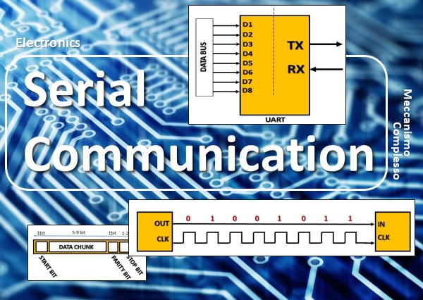
The final part of this discussion is to find something that allows us to create serial packets and control physical hardware lines: the UARTs.
An UART (Universal Asynchronous Receiver / Transmitter) is the part of the circuit responsible for serial communication. Specifically, an UART acts as an interface between serial and parallel communications. In fact, on the one hand we will have a bus of 8 lines for parallel communication and on the other side two serial outputs RX and TX.

UARTs exist as stand-alone integrated circuits (ICs), but often they may already be integrated within microcontrollers (some also have different ones). For example Arduino UNO has 1 integrated UART, Arduino Mega has 4.
So the UARTs perform some complex functions. As far as broadcasting is concerned, UARTs must create data packets, add parity and sync bits, and send them to the TX line. As far as reception is concerned, the UARTs must sample the received bits in accordance with the baud rate rules, and then delete the synchronization and parity bits by extracting the data chunks.
Conclusions
In this article, you have seen a quick overview of electronic communications between modules, which are divided into serial and parallel. In particular, you have seen the concepts and rules underlying them, and how they are actually realized through RS-232 and TTL protocols. This is just one of the first articles introducing to the electronics industry. Other articles of general interest will illustrate other concepts that are the basis of electronics.[:]