Before starting to deal with manipulators and robotics in general, it is very important to know their structure and possible configurations. Of all the possible structures created by the combination of solid bodies and joints, in fact only a few have proven effective in carrying out particular tasks. In this article we will see the most common configurations used in the industry and in the most used robotics applications.
The structure of a manipulator robot
A manipulator can be defined as a kinematic cellar consisting of:
- Rigid bodies
- Joints (rotoidal and prismatic)
The manipulator mainly identifies: a load-bearing structure that must perform the mobility functions, a wrist that adds dexterity and precision, and finally a terminal organ that performs the task, called the effective end.
A kinematic chain is also characterized by two ends. One is the base which is bound to the environment, and which has the purpose of fixing and supporting the manipulator, the other is the effective end which performs a particular function which is then the task of the manipulator.
The nature of the terminal organ depends precisely on the task that the manipulator must carry out. If this has to grab an object, move it and position it, it will certainly be a gripper. While if the manipulator will have to perform cutting or assembly operations, the terminal member can be an instrument such as a cutter, a drill or a welder.
The joints: movement and degrees of freedom of the manipulator
In order to carry out its task, the manipulator must ensure perfect movement of the terminal organ. The overall movement of a manipulator is achieved through the sum of the elementary movements of the individual rigid bodies relative to their joints.
The joints are of two types:
- prismatic
- revolute or rotoidal
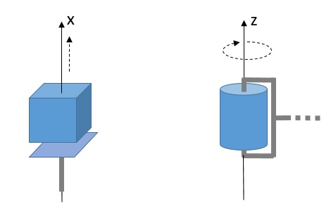
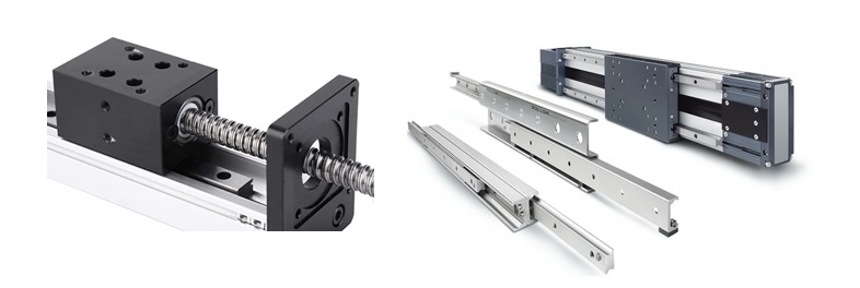
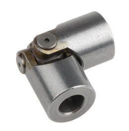
A prismatic joint is a connection between two solid bodies that allows a linear movement between them. This movement is often accomplished by the sliding of two interconnected parts.
A rotoidal joint is a connection between two solid bodies which allows rotation between them on a specific axis.
Since the manipulator is an open kinematic chain, each joint adds a degree of freedom to the system (DOF). When making a manipulator, the joints must be chosen with appropriate care and in sufficient numbers to ensure that the manipulator can carry out its task correctly.
To correctly position and orient the terminal organ in a three-dimensional space, 6 degrees of freedom are needed, of which 3 are for position and 3 are for orientation. If the manipulator has more degrees of freedom than necessary, it is said to be redundant.
When it comes to the movement of a manipulator robot it is necessary to define the workspace. This is nothing more than the portion of space in which the terminal organ can access and operate.
The most common configurations of manipulators
As we can easily guess, by varying the number and type of joints, many configurations of manipulators can be obtained. Among these are some particular configurations that have proven more efficient in performing particular tasks. In fact, depending on the particular configuration, different work spaces can be obtained.
These configurations are characterized in particular by the sequence of the joints that compose it, indicating with R for a rotoidal joint and P for a prismatic joint.
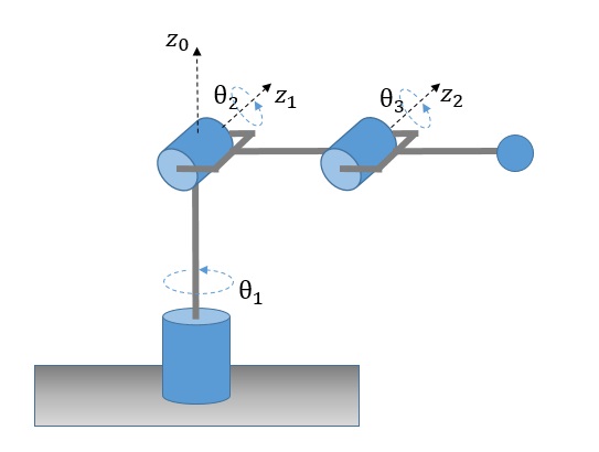
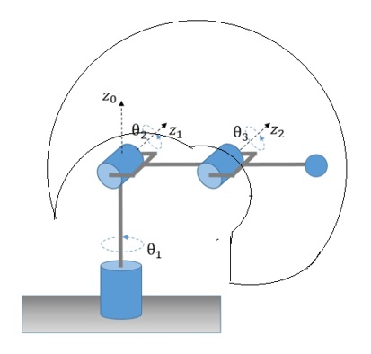
Articulated manipulator (RRR)
This type of manipulator is also called a rotary manipulator or an anthropomorphic manipulator. The abbreviation RRR indicates the three different chain joints all three rotating.
Spherical manipulator (RRP)
By replacing in the sequence of the joints, the third joint from rotating to prismatic obtains the spherical manipulator. This name derives from the fact that the spherical coordinates perfectly define the position of the effective end with respect to the point of origin that corresponds to the other end of the manipulator, i.e. the base.
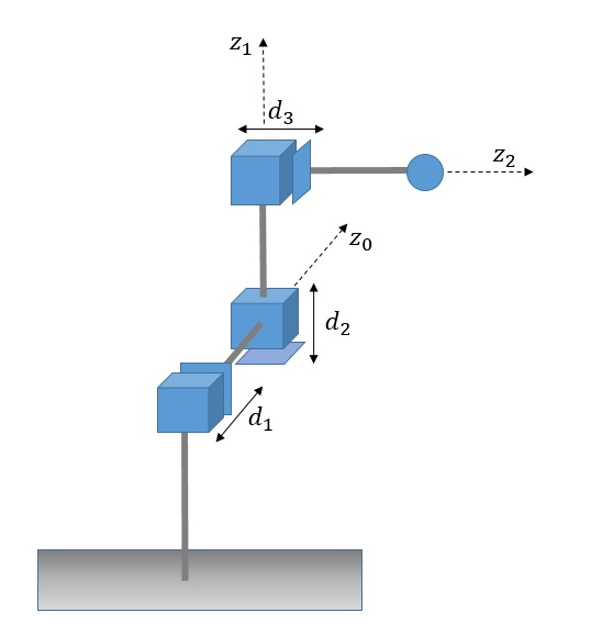
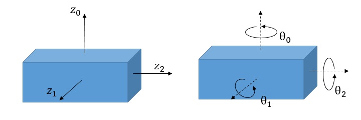
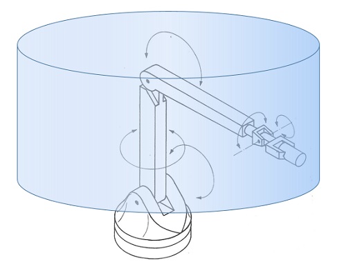
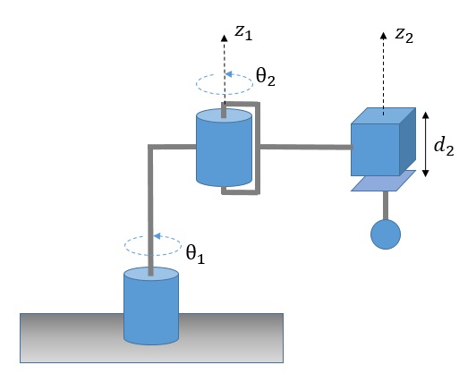
The SCARA manipulator (RRP)
The abbreviation SCARA stands for Selective Compliant Articulated Robot for Assembly, and is a type of manipulator widely used. Although the SCARA has an RRP structure of the joints identical to that of the spherical manipulator, it is different both in appearance and in the type of applications. Unlike the spherical manipulator which has the z0 axis perpendicular to the z1 axis, and the z1axis perpendicular to the z2 axis, the SCARA manipulator has the z0, z1 and z2 axes parallel to each other.

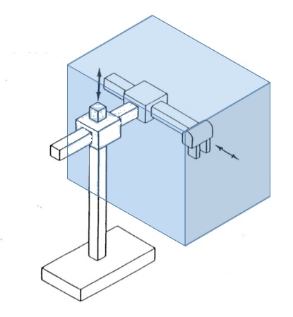
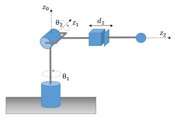
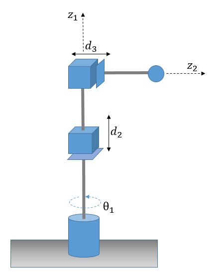
Cylindrical manipulator (RPP)
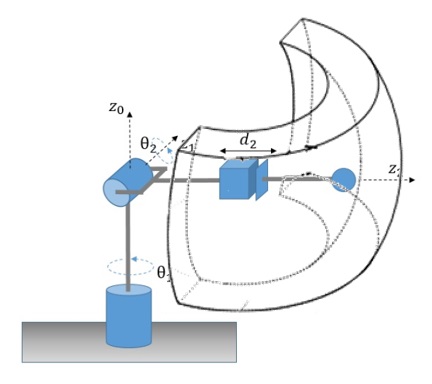
In this case only the first joint is rotating and produces a rotation around the base, while the second and third joints are prismatic.
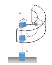
50/5000
Workspace of the cylindrical manipulator – RPP
Cartesian manipulator (PPP)
In this type of manipulator, all three joints are of the prismatic type. For this type of manipulator, the joint coordinates are nothing more than the Cartesian coordinates of the effective end with respect to the base (other end). As we can expect, the kinematic description of this manipulator is the simplest of all.