
Introduction
With this article, I will start to post a series of tutorials describing the use of several sensors, both for Arduino and for Raspberry Pi. Let’s start with a commonly used PIR sensor for detecting movement within a room or outdoors. Often, while you are walking along a garden or walking into a room, you can suddenly see a spotlight or a light turn on. Well, at the base of this there is just a PIR sensor positioned at a corner. So it’s important to know what they are and understanding how they work. In addition in the two article to follow, various examples will be shown in order to learn how to make your own projects making use of these sensors, both with Arduino and with Raspberry Pi.
PIR (Pyroelectric “Passive” InfraRed) Motion sensor
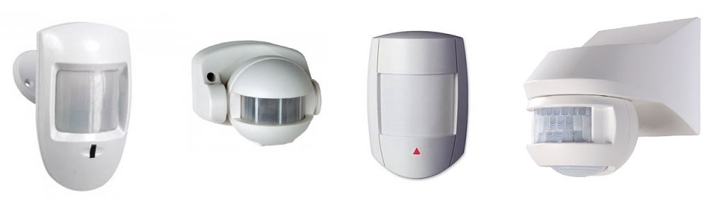
PIR are more precisely motion sensor with infrared detection. Surely you’ve seen them before now. They are often used in alarm systems or automatic lighting. Indeed those white sensors which often you glimpse positioned at the corners of the rooms, are not cameras but PIRs.
All objects above absolute zero emit infrared radiation. The infrared radiation is not percebilie by human vision, but can be detected by the electronic components within these modules.
The sensor is called passive because it does not send any signal outside to detect motion, but adjusts itself to record the infrared “signature” of the environment. Then it immediately probes the environment looking for any change. Any moving object in the room will correspond to a variation in the infrared “signature” previously detected. This variation will be read by the PIR sensor as a movement and signaled to the receiving system.
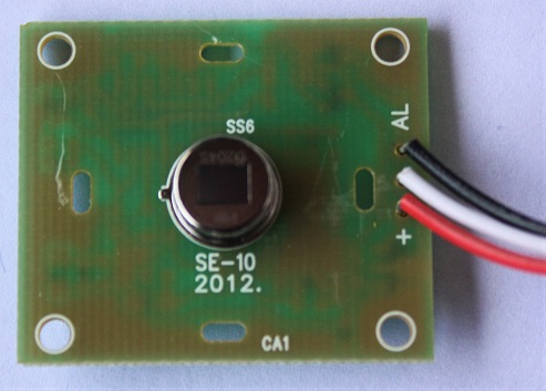
As regards Arduino and Raspberry Pi, PIR modules are commercially available at a low price online. These PIR modules are very cheap and their small dimensions allow them to be easily used in your projects. The quality of these PIR sensors varies according to their sensitivity, and especially for the detection distance ( Better the quality higher the price). The figure below shows one of these PIR modules PIR, more precisely, the SE-10 model(datasheet).
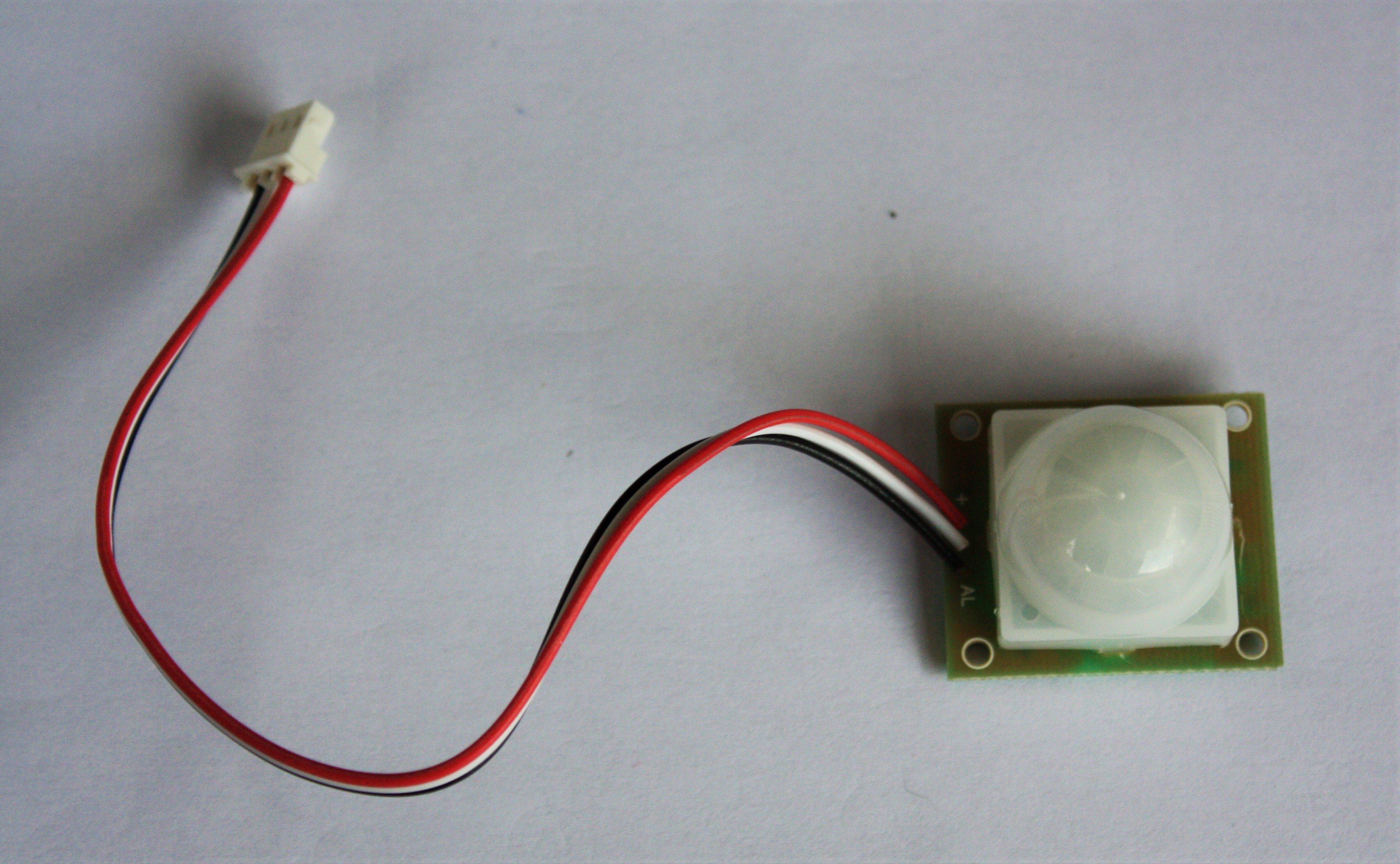
This sensor works perfectly with 5-12V. Once the PIR is powered it will take 1 or 2 seconds to make a infrared “snapshot” of the surrounding enviroment, then any changes will be reported as a movement.
There is also another very popular model, called SR501+.
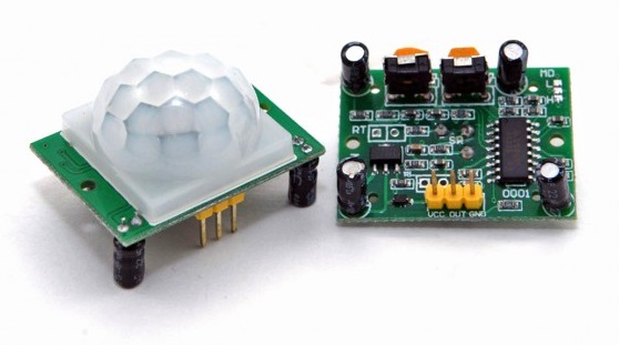
Also this sensor can be powered by a 5-12V voltage. Furthermore it has possibility of being adjusted. Indeed, the output signal, the detection distance and the delay time can be adjusted via jumpers and trimmers.
How the PIR sensor work
The actual PIR sensor is an electronic component that is located within the PIR module, and more precisely inside the white hemispherical capsule (which, as you will soon see, is a lens). After removing the capsule from the electronic board you can see the sensor in the center (as shown in the figure below).
In the top of the sensor there is a black square. This is actually a window made of infrared transparent material, generally a silicon coated film, which has mainly a protective purpose.
Below the film are two slots made of an infrared sensitive material. When the sensor is in the IDLE state (ie it is not detecting any movement), both slots are detecting the same amount of IR from the surrounding environment (room, walls, floor, etc …). If a hot body as a human being or an animal crosses in some way the “visual” field of the sensor, it will first be intercepted by one of the two slots, causing a positive differential between the two slots. When the body warm will turn away, then it will be the other slot to detect it, and so this time there will be a negative spread between the two slots. These status changes generate the pulses that in turn produce the signal transmitted by the sensor.
The following figure shows in detail how the sensor works, representing in detail the output signal with respect to external stimuli. This figure was taken from a very good article that explains in detail the functioning of these sensors. Panel A shows the signal which is produced in the two cases in which a subject is moving in two opposite directions with respect to the sensor. Panel B shows the output signal in the case of two subjects that move in the same direction but at different distances. The C pane instead shows the output signal produced by a person who moves in the same direction but at two different speeds.

But now pay attention to the white capsule that you have removed from the PIR module to observe the internal sensor. If you look at the internal part, you will notice on the surface a series of reliefs.
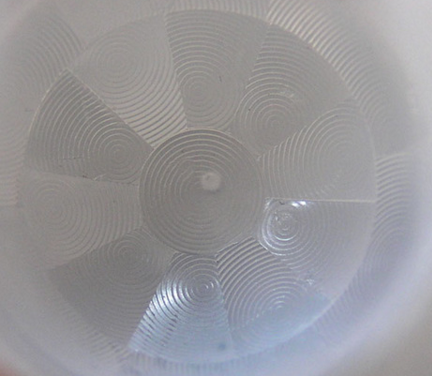
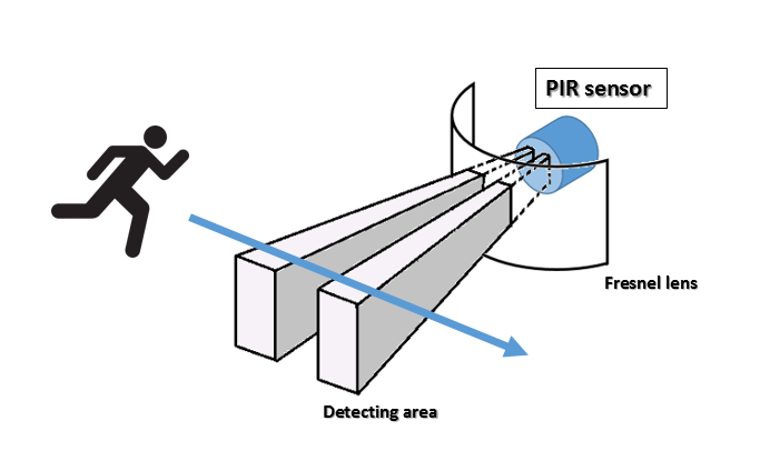
Actually the white capsule is a hemispherical lens, and more particularly a Fresnel lens. This lens has the task to expand the detection area of the two infrared detectors to a hemispherical volume that may also include an entire room. These lenses condense the infrared light coming from the surrounding volume focusing it at a certain point, which is the small black box at the top of this PIR. The interesting thing is that even though these lenses are made of simple plastic created in molds, work fine. This allows for modules PIR truly low cost.
Here is a clear scheme of what you have just read (see here).
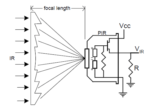
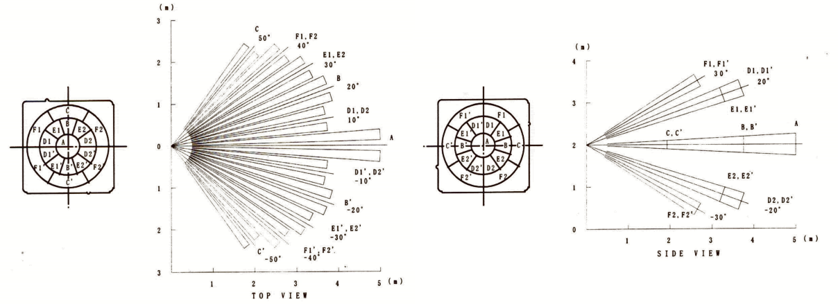
In the scheme above it is represented a flat lens. Actually the capsule mounted on the RIP module has a hemispherical shape and if you look carefully you will notice that it is composed of many Fresnel planes. This was done in order to capture and focus the infrared radiation coming from more possible directions. In the following figure you can see the mapping of the model NL11NH Fresnel lens as shown in its datasheet.
How to connect the PIR module
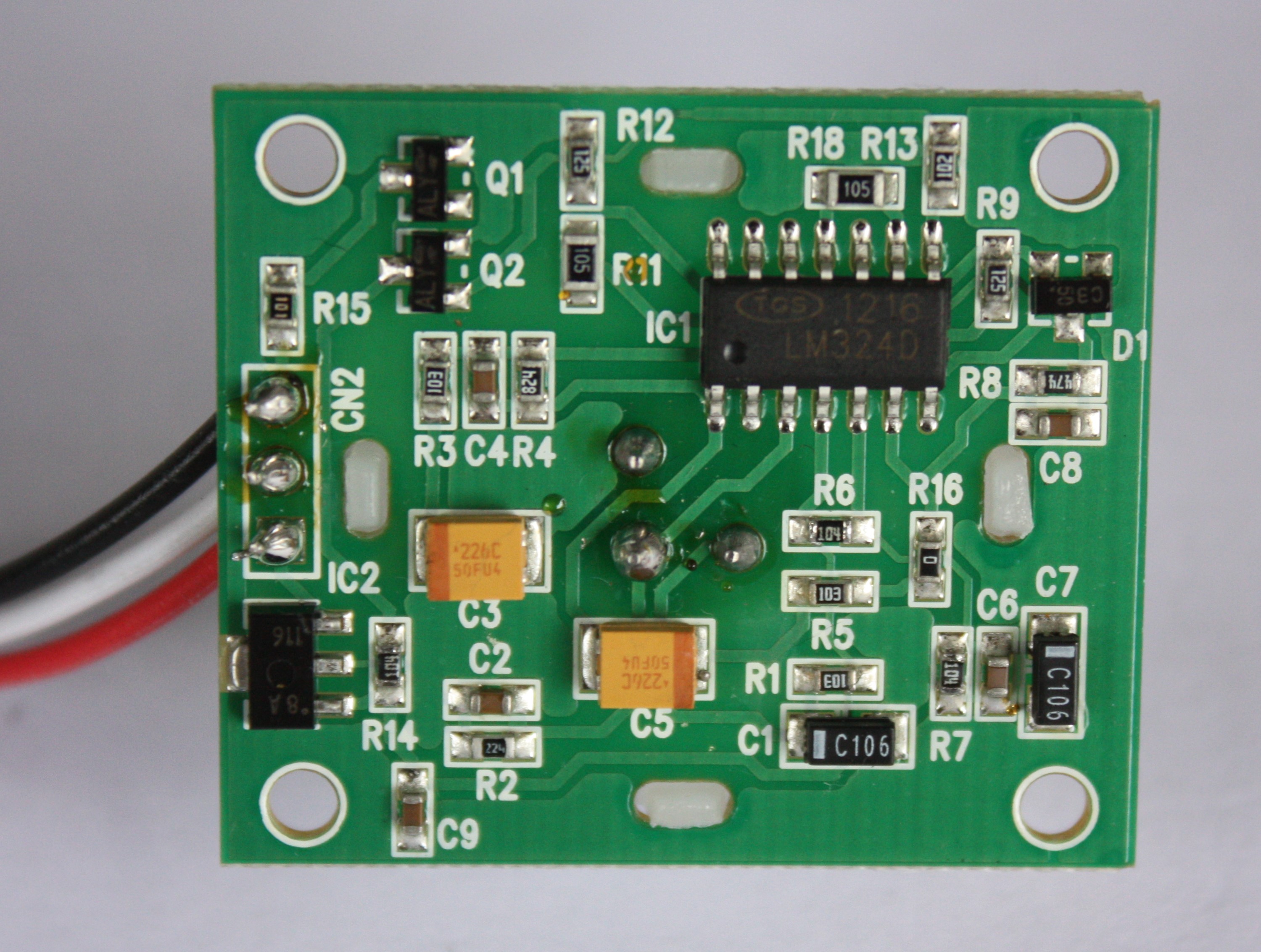
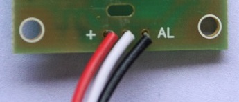
All PIR modules are characterized by three outgoing cables connected to three PIN placed on the edge of the board. A pin is for the power supply +5V, a pin is the GND, and the last is for the detection signal (ALARM). This PIN will emit a signal every time a movement is detected by the PIR sensor.
You will exploit this voltage variation, ie the signal, to transmit to a Raspberry Pi, an Arduino, or other boards, the information on a relative movement. These boards waiting for a voltage variation, will be activated by acting accordingly, depending on the program in execution.
However, you will need to pay attention to the fact that each PIR model has its color pattern for the cables functionality. Even the order of the PIN is not always the same, so I recommend you consult the datasheet of your PIR model, in order to avoid problems during the connection.
In my case, that is with the SE-10 model, I have this arrangement of the PINs.
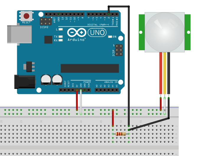
For the preparation of electronic diagrams, generally I use the Fritzing application. Fritzing is a beautiful freeware software that allows you to create electronic diagrams and truly attractive graphics for tutorials. If you are an fan for Arduino or Raspberry tutorials you have certainly seen graphical representations made with this software. If you are interested I suggest you read this article about Fritzing.

The PIR sketch of the corresponding module can be easily imported in Fritzing. You can import it from the adafruit project on github (click here for see the PIR module file, and then go to “raw” to directly download it).
Conclusions
Now that you have some familiarity with the PIR sensor, in future articles you will see how to make your projects with Arduino or Raspberry. Through simple tutorials, the basics of the sensor functionalities will be explained along with the commands you have to use during the code implementation. In addition some possible applications of the PIR sensors will be shown. See you soon then![:]