Introduction
Welcome to the third and final part of the article.
For those who have not yet read the first and second part, you can reach it through these links:
In this section we will cover the following topics:
- Using a circuit
- Programming in Python
- Series of examples
- Tips’n’tricks
The circuit
The circuit that we will use for the first test, will consist simply of an LED low power and a resistance. We will use the 3.3 V pin of the ‘comb’ and a GPIO of the Raspberry Pi to close the circuit to ground. Nothing prevents to do the opposite, that is, you can use a GPIO to provide power and the 0V pin of the ‘comb’ as ground. In my case I chose the first option because I use an RGB LED anode (positive) common.

The resistor R1 is calculated using the formula:

This formula is nothing more than the Ohm’s law[+] in which the voltage across the resistor is calculated as the subtraction between the supply voltage (3.3 V) and the voltage drop of the LED.
For example, if you have an LED whose voltage drop is 1.6 V, and you want its current to be 8mA, you will calculate the resistance in this way:

It becomes 220Ω if we consider the commercial values[+].
If you do not know the value of the voltage drop of the LED, you can easily find it with a multimeter (tester).

If you use larger voltages for the test (eg 12V) the resistance must in turn be larger (at least 2kΩ).
If you do not know the current which must be supplied to the LED, a current of 4-8 mA generally goes well. If you do not want to take any chances, use a resistor of 1kΩ and if the LED does not light up, try to get down to 470Ω. Obviously, first verify that the LED is connected in the right way (the shorter leg to the ground and the longest to the positive pin).
The second circuit that we will make, serves to test the inputs of Raspi board and it is composed only of a button. You will also use this circuit to see how to use inputs and outputs of Raspi simultaneously.
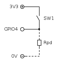
Rpd is the pull-down resistor, which serves to give a logic signal reference to the GPIO. If this were absent when SW1 is open, the GPIO would be effectly disconnected from the circuit, not having neither a positive nor a negative reference. Thus the GPIO could “invent” the status of giving false readings. The Rpd resistor makes sure that when the button is open the GPIO is connected to ground, leaving therefore a logic signal always precise.
In the circuit sketch the branch of Rpd is dashed because you will use the internal resistor of the BCM2835. However, the pull-down and pull-up resistors are present in many digital electronic circuits and it is important to understand how they work. An interesting experiment is to try reading the inputs without pull-up/pull-down resistors and see how actually the minimum electrical noise generates false readings in the program.
Python
Here you are at the point where you learn to control the outputs. Python already incorporates a library called RPi.GPIO that allows you to control the outputs and read inputs.
The interpreter
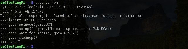
Let’s see how to turn on the LED of the first circuit. We launch python with the commandsudo python
sudo is necessary to allow the interpreter to access the GPIO control.
At this point you can run commands directly from the python interpreter.

Now write the following commands:
import RPi.GPIO as gpiogpio.setmode(gpio.BCM)
gpio.setup(3, gpio.OUT, initial=1)
gpio.output(3, 0)
gpio.output(3, 1)
gpio.cleanup()
exit()
And here’s what they do:
import RPi.GPIO as gpio
It tells python to load the RPi.GPIO library. You need this library to manage the pins of the BCM2835. From now on we will refer to this library simply by gpio.
gpio.setmode(gpio.BCM)
It calls the setmode function of the library, and specifies that, during the execution, the GPIOs will be selected referring to the number of pin-outs of the microprocessor (BCM mode) rather than with the number of pins of the comb (BOARD mode). The choice of method depends on the personal taste and the difference between them lies in the fact that, if you write complex programs and loaded them on different Raspberry Pi revision, using the BCM mode, you need to change the number of the pin connected according to the specifications of each revision, while using the BOARD mode, the program will work regardless of the connection of the microprocessor[+].
gpio.setup(3, gpio.OUT, initial=1)
It configures the pin called GPIO3 (see diagram in the Hardware section of the article-part 1) as an output and sets the port status to a high logic level (3.3 V). In this way, the LED remains off.
gpio.output(3, 0)
It changes the state of GPIO3 to a low logic level, which electrically corresponds to 0V. At this point, if the circuit is done correctly, the LED will light up.
gpio.output(3, 1)
It restores the state of the GPIO3 to high logic level (3.3 V). The LED turns off.
gpio.cleanup()
It deletes all configurations we have done and restore all the GPIO that we used to default values.
exit()
It closes the interpreter. In its place, you can also use Ctrl + D.
The gpio.output command takes as arguments channel and state, where state can be 1 or 0, but also True or False.

Now let’s try the second circuit to verify the operation of the inputs.
The initial and final commands are the same, but they change in the phase of reading:
import RPi.GPIO as gpiogpio.setmode(gpio.BCM)
gpio.setup(4, gpio.IN, pull_up_down=gpio.PUD_DOWN)
gpio.wait_for_edge(4, gpio.RISING)
gpio.cleanup()
exit()
In short:
import RPi.GPIO as gpio e gpio.setmode(gpio.BCM)
you have already seen it in the example above.
gpio.setup(4, gpio.IN, pull_up_down=gpio.PUD_DOWN)
It specifies that the GPIO4 must be configured as input and its pull-down resistor must be activated.
gpio.wait_for_edge(4, gpio.RISING)
The interpreter waits for the GPIO4 changes logic state, and moves from low to high level status (RISING). This is the right time to press the button SW1.
gpio.cleanup()
exit()
they close the program as in the previous example.
During the setup of the gpio you can choose whether to use the pull-up resistor, pull-down resistor or neither. pull_up_down could be gpio.PUD_DOWN for the pull-down resistor or gpio.PUD_UP for the pull-up resistor. To deactivate the internal resistors you can omit this part of the command, closing the parentheses immediately after gpio.IN.
gpio.wait_for_edge can be configured to wait for the rising edge (gpio.RISING), the falling edge (gpio.FALLING) or both (gpio.BOTH).
For other methods for reading the inputs, read here.
Remember that if you are having reading problems and you can not to use the command gpio.wait_for_edge can stop running the interpreter with the shortcut Ctrl + D.
My first program
Now that you’re starting ‘to taste a bit of of the raspberries’, it is time to move on to something even more tasty. You will start by writing a simple program to turn on a LED pushing the SW1.
First of all you need an editor to write your program. The nano command (pre-installed on Raspbian) launches a simple and intuitive graphical editor. Now you will use this editor, but if you are professional programmer, you probably enjoy the vim editor. Even if it is really few intuitive, vim is highly configurable and usually once you learn how to use it you will not leave it anymore.
But let’s briefly see the nano as editor. Type the commandnano
and then press [ENTER]. You’ll see a blank screen with a menu at the bottom.

The symbol ^ indicates you need to press Ctrl together with the letter that follows. So to get out (and save) you have to use the key combination Ctrl + X.
Exit nano and create a file containing our program, which you call, in this example, first.py (where .py is the extension of a python file )touch first.py
and then open it immediately with nanonano first.py
You can think about the python code as a list of commands which you previously entered directly in the python interpreter. In fact, in the code, you will find the same commands that you have already used.
To write the program you will start by loading the necessary libraries (they are RPi.GPIO and time for the wait function). Then you will configure the two GPIO used in the circuit and you will start an infinite loop in which the program reads the input status and change the output accordingly.
Such a thing can already work:
#! /usr/bin/python
import time                                             # Import the librery to manage time

# Inizializzazione GPIO
import RPi.GPIO as gpio                                 # Import the GPIO library
gpio.setmode(gpio.BCM)                                  # BCM mode
gpio.setwarnings(False)                                 # Unable the warning messages

gpio.setup(3, gpio.OUT, initial=1)                      # GPIO3 output, default: 1
gpio.setup(4, gpio.IN, pull_up_down=gpio.PUD_DOWN)      # GPIO4 input, enable pull-down

print("Ready!")

# Infinite loop
while 1:
       if gpio.input(4):                                # If input is HIGH turn on the LED
               gpio.output(3, 0)
       else:                                            # Else turn off it
               gpio.output(3, 1)
       time.sleep(0.05)                                 # Wait 50ms
The very first line is a special comment and it is used to run the script from the terminal. It is a way to explain to the terminal that the script must be interpreted with the program that is located at /usr/bin/python, which is the usual interpreter.
In the initialization phase of the GPIO, there is a new command: gpio.setwarnings. You can have multiple scripts running at one time and if python detects that a pin that we are going to configure, is not in the default state (input), it warns us that there may be a conflict between programs. You can disable the alerts by placing True in brackets, or False if, instead, you want enable them.
The print command writes the contents of the brackets on terminal and in this case we use this command as a feedback for informing us that the program has finished initializing.
The while statement marks the beginning of a loop, which ends when the condition becomes false. In this case you want an infinite loop and therefore you have to set the condition to 1 (interpreted as 1 = 1) that is always true.
Inside the while loop an if … else statement is placed. It tests the input GPIO4. If the input is true (HIGH), which means that the button is pressed, the output GPIO3 is turned off, lighting so the LED. Otherwise the output is set to the high level, turning off the LED.
At the end of the script I added the sleep function which stops the execution of the script for 50ms to allow the CPU to handle other processes.
Note that the syntax of python is extremely simple. There are no semicolons, there are no commands to exit the while loop or the if test. In this language the beginning and the end of the command are determined by indentation. If the function time.sleep had been written in the same column of the while, python would have interpreted that statement as out of the loop.
Once you have finished to write the script, press Ctrl + X and then Y to save changes. Then confirm the name of the file, press [ENTER] to exit from nano and go back to the terminal.
At this point you have just to make the script executable with:chmod u+x first.py
now you can run it with:sudo python first.py
or withsudo ./first.py
When you are satisfied with the test press Ctrl + C to stop execution of the script.

Other examples
SWITCHING OFF DELAY
This program, very similar to the first, waits till you press and hold the button to turn the LED on for two seconds.
#! /usr/bin/python
import time                                         # Import the library to manage timer

# GPIO Initialization
import RPi.GPIO as gpio                             # Import the GPIO library
gpio.setmode(gpio.BCM)                              # BCM mode
gpio.setwarnings(False)                             # Disable warning messages

gpio.setup(3, gpio.OUT, initial=1)                  # GPIO3 output, default: 1
gpio.setup(4, gpio.IN, pull_up_down=gpio.PUD_DOWN)  # GPIO4 input, enable pull-down

print("Ready!")

# Infinite loop
while 1:
     gpio.wait_for_edge(4, gpio.RISING)              # Wait for the rising edge
     gpio.output(3, 0)                               # Turn on the LED
     time.sleep(2)                                   # Wait 2s
     gpio.output(3, 1)                               # Turn off the LED
BLINKING CONTROLLED BY A BUTTON (WITH DEBOUNCE)
In this example, instead, you blink an LED every 0.5 seconds when the key is pressed and you will stop the blinking when the key is pressed again. This script uses interrupts and a debounce check for the button.
#! /usr/bin/python
import time                                         # Import the librery to manage timers

# GPIO Initialization
import RPi.GPIO as gpio                             # Import the GPIO library
gpio.setmode(gpio.BCM)                              # BCM mode
gpio.setwarnings(False)                             # Disable warning messages

gpio.setup(3, gpio.OUT, initial=1)                  # GPIO3 output, default: 1
gpio.setup(4, gpio.IN, pull_up_down=gpio.PUD_DOWN)  # GPIO4 input, enable pull-down

# Variables
lampeggio = False                                   # Memory of blinking

# Functions
def cambia_stato(pin):
    global lampeggio                                # Import the global variable lampeggio
    if lampeggio:                                   # If the blinking is enabled
        lampeggio = False                           #  disable blinking
        gpio.output(3, 1)                           #  turn off the LED
    else:                                           # Else
        lampeggio = True                            #  enable blinking
        gpio.output(3, 0)                           #  turn on the LED

# Interrupt
# Insert an event causing the calling to "cambia_stato" function
# whenever a raising edge is detected on pin 4
gpio.add_event_detect(4, gpio.RISING, callback=cambia_stato, bouncetime=200)

print("Ready!")

# Infinite loop
while 1:
    if lampeggio:                                   # If the blinking is enabled
        if gpio.input(3):                           #  If the LED is off
            gpio.output(3, 0)                       #   turn on the LED
        else:                                       #  Else
            gpio.output(3, 1)                       #   turn off the LED
    time.sleep(0.5)                                 # Wait 0.5s
This script is not as complicated as it sounds: after the usual initialization a variable lampeggio is defined. This variable stores information whether you turn on or off the blinking. Initially, the flash is disabled.
After the variable you find the cambia_stato function. This part of the code is called each time the button is pressed and changes the state of the lampeggio variable as well as turns on or of the LEDs depending on the conditions.
The statement global lampeggio is necessary to allow the function to change the value of the lampeggio variable, which would otherwise be used as read-only.
After few lines of code, you find the declaration of the interrupt. Interrupts allow you to interrupt the main program (the part of code inside the while loop) and then run other parts of code (in this case the cambia_stato function). Once the function has been executed the main program continues from where it was interrupted.
The statement add_event_detect takes as arguments the GPIO on which to perform the test (GPIO4), the condition of detection (gpio.RISING that is the rising edge), the function to call (cambia_stato) and the bouncetime (optional).
The bouncetime is used when you are working with mechanical buttons. it is a small timer (in this case 200ms) that suppresses the bounce of the key to avoid reading more rising edges at a single press of the button.

After the declaration of the interrupt you find the main section of the script that controls the lampeggio variable. If this is true (and then blinking is activated), this part of code checks the output status of the LED (yes, you should use gpio.input for this!) and reverses it. If the lampeggio variable is false, the LED is turned off (it is turned off the first time during the cambia_stato function). Before to start the loop again, the program waits half a second to allow us to see the LED blinking.
These programs do not have the gpio.cleanup function at the end, because it is expected you interrupt them by the keyboard. If you write a program with an end (no infinite loop) ,instead, you have to enter this command.
THERE IS A MAIL FOR YOU
This little program is only for Gmail accounts and uses the feedparser module of python to control the number of unread emails in your inbox. Because you have to enter username and password, be careful not to copy the program in unsafe places … like the internet indeed.
First you have to download the feedparser library which by default is not installed. Let’s go on the page of the python module, which you can find here, and download the file .tar.bz2. But do not download it on your pc (because Windows does not know what is a tar file), download it directly on the Raspberry Pi.wget link
where you must obviously replace the word ‘link‘ with the link to the tar.bz2 file.
Once wget ends to download the file, unzip it with:tar -xf nome_del_file
(remember the autocomplete function: enter the first few letters of the file and press TAB twice).
At this point, if you call the ls command you will find a new directory with the same name of the file you downloaded. Move in it (cd) and enter the commandsudo python setup.py install
In a few seconds you will have installed the new module.
While I was doing these steps, I launched the setup of the module and python told me that he lacked the setuptools library. If it happens, repeat the procedure above with the file downloaded from here and once installed, resume the installation of feedparser.
Now let’s see the code:
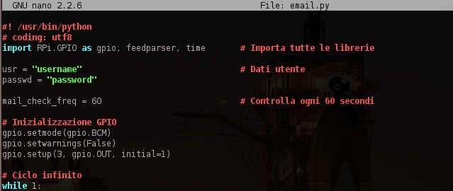
#! /usr/bin/python
import RPi.GPIO as gpio, feedparser, time   # Import the libraries

usr = "username"                            # User Data (username without @gmail.com)
passwd = "password"

mail_check_freq = 60                        # Check every 60 seconds

# GPIO Initialization
gpio.setmode(gpio.BCM)
gpio.setwarnings(False)
gpio.setup(3, gpio.OUT, initial=1)

# Infinite Loop
while 1:

    # Check the mail number
    newmail = int(feedparser.parse("https://" + usr + ":" + passwd +"@mail.google.com/gmail/feed/atom")["feed"][fullcount"])

    if not newmail:                         # If there are not new emails
        gpio.output(3, 1)                   #  turn off the LED
    else:                                   # Else
        gpio.output(3, 0)                   #  turn on the LED

    time.sleep(mail_check_freq)             # Wait for the mail_check_freq value
In addition to the usual things (import libraries, setup of GPIO), there are three variables configurable by the user: username, password and mail_check_freq. The first two are used to authenticate the user with the login for Gmail, while the third determines how often (seconds) the mailbox should be checked.
Within the loop, the first function that uses feedparser extracts the number of unread emails from Google RSS feed and stores it into the newmail variable.
The newmail variable is checked and if it is zero (which is equivalent to False, that’s why you use a boolean control) the LED is turned off, otherwise it is turned on. Then the script is paused for the time established by the variable mail_check_freq. The difficulty in this script is to extrapolate from the feed the number of unread emails. For more information on how feedparser works click here.
Tips ‘n’ Tricks – part 2
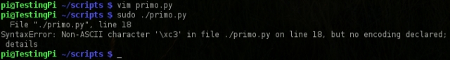
NON-ASCII CHARACTER
Sometimes it can happen that, while you are copying and pasting text from a script, some unrecognizable characters end up in the middle of the file and then saved. If it happens, launching the program it will show the message ‘no encoding declared’.
The workaround is to specify the text encoding (utf8 is fine) to python by inserting at the beginning of the program (but still within the special comment #!) the following line:
# coding: utf8
SYNTAX RECOGNITION FOR PYTHON WITH NANO
Nano is ugly and gray by default, but fortunately you can highlight the syntax of some languages with him. If you want to know what are the languages, just look into the folder /usr/share/nano (always with the command ls). Among them you will also find the file python.nanorc.
To activate the recognition of the syntax, you have to create the hidden file .nanorc in your home directory and then enter the include command followed by the location of the file you are interested. If you want to overdo it and do it all in one command (be sure to be in home):echo "include /usr/share/nano/python.nanorc" > .nanorc
At the next restart of nano, you’ll be more or less like:
LAUNCH A SCRIPT AT STARTUP
And if you want to run a program as soon as the Raspberry Pi is turned on? Nothing could be easier! Make sure your program is executable (check with ls -l if the file is marked with x) and note its path (absolute). If you have any questions about your path, the command:pwd
will return the absolute path of the directory containing the script.
At this point, you can edit the file /etc/rc.local. This file contains the list of commands to be run at startup.sudo nano /etc/rc.local
Once you have opened it, you find a lot of comments, a small function for obtaining the IP address of the Raspberry Pi, and the exit 0 command. Insert the path preceded by sudo between the existing function ( you can also remove it) and the exit 0 command (which is rather important and should be left at the bottom of the file).
Save the file and reboot the system (sudo reboot), the program will start automatically.

If you have startup problems and the script doesn’t run, you can try to enter the python command between sudo and the path of the script.
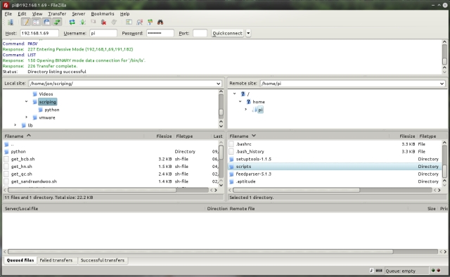
FTP SERVER
If you prefer the editor on your PC instead of nano or vim, this is a method to send the file that you have already prepared on your pc, to Rasperry Pi and then run it from the terminal. You can quickly install the FTP server with:sudo aptitude install ftpd
After about a minute, the server is already configured and ready, you cab verify if it is working using the command:netstat -lt
It shows which ports are open. If all goes as planned, you will find services listening on port 21 (ftp) and 22 (ssh).
At this point, download a FTP client such as FileZilla, insert username and password of the Raspberry Pi (specify the port only if it is other than 21) and connect by clicking on “Quickconnect“.
Now you can browse between directories of Raspi and exchange files quickly and easily.
LOGIN WITHOUT PASSWORD
(only Linux)
As I mentioned a few hundred lines ago, the SSH protocol uses a type of public key authentication, which means, among other things, that if you have a pair of keys (public and private) you can access to Raspi using our private key. I will not explain how authentication works, but if you’re interested (and it would be nice that you were) there are already thousands of articles on Internet just waiting to be found by a Google search.
If you still do not have a pair of keys, generate them (on your PC, not on the Raspberry Pi!) With the commandssh-keygen -t rsa
Save your key with the default steps and, when prompted, leave blank the passphrase fields, otherwise you will be prompted for a password, making the whole operation effectively useless.
Once you have done, upload the public key on Raspi launching (again from the pc) the command:ssh-copy-id -i ~/.ssh/id_rsa.pub pi@ipaddress
You will be prompted for the password of the pi user, to be sure that the copy of the public key is performed by a user who has access to the Raspberry Pi. Finished this step, try to login with the commandssh pi@ipaddress
and if all goes well, you directly enter.

Conclusions
We explored a bit of python and see the basics for working with GPIOs. The article is long, but I hope I have satisfied the needs of novices and to have tickled your curiosity if you are discovering the Raspberry Pi for the first time.
There are lots of things I wanted to add in this article, for example, many features that I’m trying with as many programs but unfortunately I can not write here as a matter of space.
I hope to have a short enough material to put together a new article of practical examples and see how best to exploit the capabilities of this little computer.
The thing that concerns me and that I hope you undestood is that the Raspberry Pi has incredible potential. It is really easy to use and there are thousands of projects on the internet from which to take inspiration.
I did my best to document everything that I wrote, but if you find inaccuracies please leave a comment and I will try to fix the article.[:]